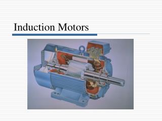
Lecture 5: DC motors
1.31k likes | 3.04k Vues
Lecture 5: DC motors. Instructor: Dr. Gleb V. Tcheslavski Contact: gleb@ee.lamar.edu Office Hours: TBD ; Room 2030 Class web site: http://ee.lamar.edu/gleb/Index.htm. Preliminary notes.

Lecture 5: DC motors
E N D
Presentation Transcript
Lecture 5: DC motors Instructor: Dr. Gleb V. Tcheslavski Contact:gleb@ee.lamar.edu Office Hours: TBD; Room 2030 Class web site:http://ee.lamar.edu/gleb/Index.htm
Preliminary notes DC power systems are not very common in the contemporary engineering practice. However, DC motors still have many practical applications, such automobile, aircraft, and portable electronics, in speed control applications… An advantage of DC motors is that it is easy to control their speed in a wide diapason. DC generators are quite rare. Most DC machines are similar to AC machines: i.e. they have AC voltages and current within them. DC machines have DC outputs just because they have a mechanism converting AC voltages to DC voltages at their terminals. This mechanism is called a commutator; therefore, DC machines are also called commutating machines.
The simplest DC machine The simplest DC rotating machine consists of a single loop of wire rotating about a fixed axis. The magnetic field is supplied by the North and South poles of the magnet. Rotor is the rotating part; Stator is the stationary part.
The simplest DC machine We notice that the rotor lies in a slot curved in a ferromagnetic stator core, which, together with the rotor core, provides a constant-width air gap between the rotor and stator. The reluctance of air is much larger than the reluctance of core. Therefore, the magnetic flux must take the shortest path through the air gap. As a consequence, the magnetic flux is perpendicular to the rotor surface everywhere under the pole faces. Since the air gap is uniform, the reluctance is constant everywhere under the pole faces. Therefore, magnetic flux density is also constant everywhere under the pole faces.
The simplest DC machine 1. Voltage induced in a rotating loop If a rotor of a DC machine is rotated, a voltage will be induced… The loop shown has sides ab and cd perpendicular to the figure plane, bc and da are parallel to it. The total voltage will be a sum of voltages induced on each segment of the loop. Voltage on each segment is: (5.5.1)
The simplest DC machine 1) ab: In this segment, the velocity of the wire is tangential to the path of rotation. Under the pole face, velocity v is perpendicular to the magnetic field B, and the vector product v x B points into the page. Therefore, the voltage is (5.6.1) 2) bc: In this segment, vector product v x B is perpendicular to l. Therefore, the voltage is zero. 3) cd: In this segment, the velocity of the wire is tangential to the path of rotation. Under the pole face, velocity v is perpendicular to the magnetic flux density B, and the vector product v x B points out of the page. Therefore, the voltage is (5.6.2) 4) da: In this segment, vector product v x B is perpendicular to l. Therefore, the voltage is zero.
The simplest DC machine The total induced voltage on the loop is: (5.7.1) (5.7.2) When the loop rotates through 1800, segment ab is under the north pole face instead of the south pole face. Therefore, the direction of the voltage on the segment reverses but its magnitude reminds constant, leading to the total induced voltage to be
The simplest DC machine The tangential velocity of the loop’s edges is (5.8.1) where r is the radius from the axis of rotation to the edge of the loop. The total induced voltage: (5.8.2) The rotor is a cylinder with surface area 2rl. Since there are two poles, the area of the rotor under each pole is Ap = rl. Therefore: (5.8.3)
The simplest DC machine Assuming that the flux density B is constant everywhere in the air gap under the pole faces, the total flux under each pole is (5.9.1) The total voltage is (5.9.2) The voltage generated in any real machine depends on the following factors: 1. The flux inside the machine; 2. The rotation speed of the machine; 3. A constant representing the construction of the machine.
The simplest DC machine 2. Getting DC voltage out of a rotating loop A voltage out of the loop is alternatively a constant positive value and a constant negative value. One possible way to convert an alternating voltage to a constant voltage is by adding a commutator segment/brush circuitry to the end of the loop. Every time the voltage of the loop switches direction, contacts switch connection.
The simplest DC machine segments brushes
The simplest DC machine 3. The induced torque in the rotating loop Assuming that a battery is connected to the DC machine, the force on a segment of a loop is: (5.12.1) And the torque on the segment is (5.12.2) Where is the angle between r and F. Therefore, the torque is zero when the loop is beyond the pole edges.
The simplest DC machine • When the loop is under the pole faces: • Segment ab: • Segment bc: • Segment cd: • Segment da: (5.13.1) (5.13.2) (5.13.3) (5.13.4) (5.13.5) (5.13.6) (5.13.7) (5.13.8)
The simplest DC machine The resulting total induced torque is (5.14.1) (5.14.2) Since Ap rland (5.14.3) (5.14.4) The torque in any real machine depends on the following factors: 1. The flux inside the machine; 2. The current in the machine; 3. A constant representing the construction of the machine.
Commutation in a simple 4-loop DC machine Commutation is the process of converting the AC voltages and currents in the rotor of a DC machine to DC voltages and currents at its terminals. A simple 4-loop DC machine has four complete loops buried in slots curved in the laminated steel of its rotor. The pole faces are curved to make a uniform air-gap. The four loops are laid into the slots in a special manner: the innermost wire in each slot (end of each loop opposite to the “unprimed”) is indicated by a prime. Loop 1 stretches between commutator segments a and b, loop 2 stretches between segments b and c…
Commutation in a simple 4-loop DC machine At a certain time instance, when t = 00, the 1, 2, 3’, and 4’ ends of the loops are under the north pole face and the 1’, 2’, 3, and 4 ends of the loops are under the south pole face. The voltage in each of 1, 2, 3’, and 4’ ends is given by (5.16.1) The voltage in each of 1’, 2’, 3, and 4 ends is (5.16.2) If the induced voltage on any side of a loop is (5.16.1), the total voltage at the brushes of the DC machine is (5.16.3)
Commutation in a simple 4-loop DC machine We notice that there are two parallel paths for current through the machine! The existence of two or more parallel paths for rotor current is a common feature of all commutation schemes.
Commutation in a simple 4-loop DC machine If the machine keeps rotating, at t = 450, loops 1 and 3 have rotated into the gap between poles, so the voltage across each of them is zero. At the same time, the brushes short out the commutator segments ab and cd. This is ok since the voltage across loops 1 and 3 is zero and only loops 2 and 4 are under the pole faces. Therefore, the total terminal voltage is (5.18.1)
Commutation in a simple 4-loop DC machine At t = 900, the loop ends 1’, 2, 3, and 4’ are under the north pole face, and the loop ends 1, 2’, 3’, and 4 are under the south pole face. The voltages are built up out of page for the ends under the north pole face and into the page for the ends under the south pole face. Four voltage-carrying ends in each parallel path through the machine lead to the terminal voltage of (5.16.3) We notice that the voltages in loops 1 and 3 have reversed compared to t = 00. However, the loops’ connections have also reversed, making the total voltage being of the same polarity.
Commutation in a simple 4-loop DC machine When the voltage reverses in a loop, the connections of the loop are also switched to keep the polarity of the terminal voltage the same. The terminal voltage of this 4-loop DC machine is still not constant over time, although it is a better approximation to a constant DC level than what is produced by a single rotating loop. Increasing the number of loops on the rotor, we improve our approximation to perfect DC voltage. Commutator segments are usually made out of copper bars and the brushes are made of a mixture containing graphite to minimize friction between segments and brushes.
Problems with commutation in real DC machines 1. Armature reaction If the magnetic field windings of a DC machine are connected to the power source and the rotor is turned by an external means, a voltage will be induced in the conductors of the rotor. This voltage is rectified and can be supplied to external loads. However, if a load is connected, a current will flow through the armature winding. This current produces its own magnetic field that distorts the original magnetic field from the machine’s poles. This distortion of the machine’s flux as the load increases is called armature reaction and can cause two problems: 1) neutral-plane shift: The magnetic neutral plane is the plane within the machine where the velocity of the rotor wires is exactly parallel to the magnetic flux lines, so that the induced voltage in the conductors in the plane is exactly zero.
Problems with commutation in real DC machines A two-pole DC machine: initially, the pole flux is uniformly distributed and the magnetic neutral plane is vertical. The effect of the air gap on the pole flux. When the load is connected, a current – flowing through the rotor – will generate a magnetic field from the rotor windings.
Problems with commutation in real DC machines This rotor magnetic field will affect the original magnetic field from the poles. In some places under the poles, both fields will sum together, in other places, they will subtract from each other Therefore, the net magnetic field will not be uniform and the neutral plane will be shifted. In general, the neutral plane shifts in the direction of motion for a generator and opposite to the direction of motion for a motor. The amount of the shift depends on the load of the machine.
Problems with commutation in real DC machines The commutator must short out the commutator segments right at the moment when the voltage across them is zero. The neutral-plane shift may cause the brushes short out commutator segments with a non-zero voltage across them. This leads to arcing and sparkling at the brushes!
Problems with commutation in real DC machines 2) Flux weakening. Most machines operate at flux densities near the saturation point. At the locations on the pole surfaces where the rotor mmf adds to the pole mmf, only a small increase in flux occurs (due to saturation). However, at the locations on the pole surfaces where the rotor mmf subtracts from the pole mmf, there is a large decrease in flux. Therefore, the total average flux under the entire pole face decreases.
Problems with commutation in real DC machines In generators, flux weakening reduces the voltage supplied by a generator. In motors, flux weakening leads to increase of the motor speed. Increase of speed may increase the load, which, in turns, results in more flux weakening. Some shunt DC motors may reach runaway conditions this way… Observe a considerable decrease in the region where two mmfs are subtracted and a saturation…
Problems with commutation in real DC machines 2. L di/dt voltages This problem occurs in commutator segments being shorten by brushes and is called sometimes an inductive kick. Assuming that the current in the brush is 400 A, the current in each path is 200 A. When a commutator segment is shorted out, the current flow through that segment must reverse. Assuming that the machine is running at 800 rpm and has 50 commutator segments, each segment moves under the brush and clears it again in 0.0015 s.
Problems with commutation in real DC machines The rate of change in current in the shorted loop averages Therefore, even with a small inductance in the loop, a very large inductive voltage kick L di/dt will be induced in the shorted commutator segment. This voltage causes sparkling at the brushes.
Solutions to the problems with commutation 1. Commutating poles or interpoles To avoid sparkling at the brushes while the machine’s load changes, instead of adjusting the brushes’ position, it is possible to introduce small poles (commutating poles or interpoles) between the main ones to make the voltage in the commutating wires to be zero. Such poles are located directly over the conductors being commutated and provide the flux that can exactly cancel the voltage in the coil undergoing commutation. Interpoles do not change the operation of the machine since they are so small that only affect few conductors being commutated. Flux weakening is unaffected. Interpole windings are connected in series with the rotor windings. As the load increases and the rotor current increases, the magnitude of neutral-plane shift and the size of Ldi/dt effects increase too increasing the voltage in the conductors undergoing commutation.
Solutions to the problems with commutation However, the interpole flux increases too producing a larger voltage in the conductors that opposes the voltage due to neutral-plane shift. Therefore, both voltages cancel each other over a wide range of loads. This approach works for both DC motors and generators. The interpoles must be of the same polarity as the next upcoming main pole in a generator; The interpoles must be of the same polarity as the previous main pole in a motor. The use of interpoles is very common because they correct the sparkling problems of DC machines at a low cost. However, since interpoles do nothing with the flux distribution under the pole faces, flux-weakening problem is still present.
Solutions to the problems with commutation 2. Compensating windings The flux weakening problem can be very severe for large DC motors. Therefore, compensating windings can be placed in slots carved in the faces of the poles parallel to the rotor conductors. These windings are connected in series with the rotor windings, so when the load changes in the rotor, the current in the compensating winding changes too…
Solutions to the problems with commutation Rotor and comp. fluxes Pole flux Sum of these three fluxes equals to the original pole flux.
Solutions to the problems with commutation The mmf due to the compensating windings is equal and opposite to the mmf of the rotor. These two mmfs cancel each other, such that the flux in the machine is unchanged. The main disadvantage of compensating windings is that they are expensive since they must be machined into the faces of the poles. Also, any motor with compensative windings must have interpoles to cancel L di/dt effects.
Solutions to the problems with commutation A stator of a six-pole DC machine with interpoles and compensating windings. pole interpole
Power flow and losses in DC machines Unfortunately, not all electrical power is converted to mechanical power by a motor and not all mechanical power is converted to electrical power by a generator… The efficiency of a DC machine is: (5.36.1) or (5.36.2)
The losses in DC machines There are five categories of losses occurring in DC machines. 1. Electrical or copper losses– the resistive losses in the armature and field windings of the machine. Armature loss: (5.37.1) Field loss: (5.37.2) Where IA and IF are armature and field currents and RA and RF are armature and field (winding) resistances usually measured at normal operating temperature.
The losses in DC machines 2. Brush (drop) losses– the power lost across the contact potential at the brushes of the machine. (5.38.1) Where IA is the armature current and VBD is the brush voltage drop. The voltage drop across the set of brushes is approximately constant over a large range of armature currents and it is usually assumed to be about 2 V. Other losses are exactly the same as in AC machines…
The losses in DC machines 3. Core losses– hysteresis losses and eddy current losses. They vary as B2 (square of flux density) and as n1.5 (speed of rotation of the magnetic field). 4. Mechanical losses – losses associated with mechanical effects: friction (friction of the bearings) and windage (friction between the moving parts of the machine and the air inside the casing). These losses vary as the cube of rotation speed n3. 5. Stray (Miscellaneous) losses – losses that cannot be classified in any of the previous categories. They are usually due to inaccuracies in modeling. For many machines, stray losses are assumed as 1% of full load.
The power-flow diagram On of the most convenient technique to account for power losses in a machine is the power-flow diagram. For a DC motor: Electrical power is input to the machine, and the electrical and brush losses must be subtracted. The remaining power is ideally converted from electrical to mechanical form at the point labeled as Pconv.
The power-flow diagram The electrical power that is converted is (5.41.1) And the resulting mechanical power is (5.41.2) After the power is converted to mechanical form, the stray losses, mechanical losses, and core losses are subtracted, and the remaining mechanical power is output to the load.
Equivalent circuit of a DC motor The armature circuit (the entire rotor structure) is represented by an ideal voltage source EA and a resistor RA. A battery Vbrush in the opposite to a current flow in the machine direction indicates brush voltage drop. The field coils producing the magnetic flux are represented by inductor LF and resistor RF. The resistor Radj represents an external variable resistor (sometimes lumped together with the field coil resistance) used to control the amount of current in the field circuit.
Equivalent circuit of a DC motor Sometimes, when the brush drop voltage is small, it may be left out. Also, some DC motors have more than one field coil… The internal generated voltage in the machine is (5.43.1) The induced torque developed by the machine is (5.43.2) Here K is the constant depending on the design of a particular DC machine (number and commutation of rotor coils, etc.) and is the total flux inside the machine. Note that for a single rotating loop K = /2.
Magnetization curve of a DC machine The internal generated voltage EA is directly proportional to the flux in the machine and the speed of its rotation. The field current in a DC machine produces a field mmf F = NFIF, which produces a flux in the machine according to the magnetization curve. or in terms of internal voltage vs. field current for a given speed. To get the maximum possible power per weight out of the machine, most motors and generators are operating near the saturation point on the magnetization curve. Therefore, when operating at full load, often a large increase in current IF may be needed for small increases in the generated voltage EA.
Motor types: Separately excited and Shunt DC motors Note: when the voltage to the field circuit is assumed constant, there is no difference between them… Separately excited DC motor: a field circuit is supplied from a separate constant voltage power source. Shunt DC motor: a field circuit gets its power from the armature terminals of the motor. For the armature circuit of these motors: (5.45.1)
Shunt motor: terminal characteristic A terminal characteristic of a machine is a plot of the machine’s output quantities vs. each other. For a motor, the output quantities are shaft torque and speed. Therefore, the terminal characteristic of a motor is its output torque vs. speed. If the load on the shaft increases, the load torque load will exceed the induced torque ind, and the motor will slow down. Slowing down the motor will decrease its internal generated voltage (since EA = K), so the armature current increases (IA = (VT – EA)/RA). As the armature current increases, the induced torque in the motor increases (since ind = KIA), and the induced torque will equal the load torque at a lower speed . (5.46.1)
Shunt motor: terminal characteristic Assuming that the terminal voltage and other terms are constant, the motor’s speed vary linearly with torque. However, if a motor has an armature reaction, flux-weakening reduces the flux when torque increases. Therefore, the motor’s speed will increase. If a shunt (or separately excited) motor has compensating windings, and the motor’s speed and armature current are known for any value of load, it’s possible to calculate the speed for any other value of load.
Shunt motor: terminal characteristic – Example Example 5.1: A 50 hp, 250 V, 1200 rpm DC shunt motor with compensating windings has an armature resistance (including the brushes, compensating windings, and interpoles) of 0.06 . Its field circuit has a total resistance Radj + RFof 50 , which produces a no-load speed of 1200 rpm. The shunt field winding has 1200 turns per pole. a) Find the motor speed when its input current is 100 A. b) Find the motor speed when its input current is 200 A. c) Find the motor speed when its input current is 300 A. d) Plot the motor torque-speed characteristic.
Shunt motor: terminal characteristic – Example The internal generated voltage of a DC machine (with its speed expressed in rpm): Since the field current is constant (both field resistance and VT are constant) and since there are no armature reaction (due to compensating windings), we conclude that the flux in the motor is constant. The speed and the internal generated voltages at different loads are related as Therefore: At no load, the armature current is zero and therefore EA1 = VT = 250 V.
Shunt motor: terminal characteristic – Example a) Since the input current is 100 A, the armature current is Therefore: and the resulting motor speed is: b) Similar computations for the input current of 200 A lead to n2 = 1144 rpm. c) Similar computations for the input current of 300 A lead to n2 = 1115 rpm. d) To plot the output characteristic of the motor, we need to find the torque corresponding to each speed. At no load, the torque is zero.