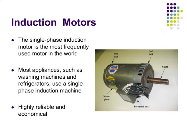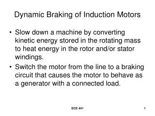
INDUCTION MOTORS 3
INDUCTION MOTORS 3. INDUCTION MOTOR MAXIMUM TORQUE. maximum power transfer occurs when: R 2 /s=√R TH ^2 + (X TH +X 2 )^2 (1) solving (1) for slip s max = R 2 / √R TH ^2 + (X TH +X 2 )^2 (2)

INDUCTION MOTORS 3
E N D
Presentation Transcript
INDUCTION MOTORMAXIMUM TORQUE • maximum power transfer occurs when: R2/s=√RTH^2 + (XTH+X2)^2 (1) solving (1) for slip smax=R2 / √RTH^2 + (XTH+X2)^2 (2) Note: slip of rotor (at maximum torque) ~ R2 rotor resistance applying this value of slip to torque equation
INDUCTION MOTORMAXIMUM TORQUE • This maximum torque ~ VTH ^2 (or square of supply voltage) & inversely related to stator Impedances & rotor reactance • The smaller a machine’s reactance the larger its maximum torque • Note:smax ~ R2 , however maximum torque is independent of R2 • Torque-speed characteristic of a wound-rotor induction motor shown if figure next
INDUCTION MOTORMAXIMUM TORQUE • Effect of varying rotor resistance on T-ω of wound rotor
INDUCTION MOTORMAXIMUM TORQUE • as the value of external resistor connected to rotor circuit of a wound rotor through slip rings is increasedthe pullout speed decreased,howeverthe maximum torque remains constant • Advantage can be taken from this characteristic of wound-rotor induction motors to start very heavy loads • If a resistance inserted into rotor circuit, Tmaxcan be adjusted to at starting conditions • And while load is turning,extra resistance can be removed from circuit,& Tmax move up to near synchronous speed for regular operation
INDUCTION MOTOREXAMPLE(1) • A 2 pole, 50 Hz induction motor supplies 15kW to a load at a speed of 2950 r/min. • What is the motor’s slip? • What is the induced torque in the motor in Nm under these conditions? • What will the operating speed of the motor be if its torque is doubled? • How much power will be supplied by the motor when the torque is doubled?
INDUCTION MOTOREXAMPLE(1)-SOLUTION (a) nsync= 120fe/p= 120x50/2=3000 r/min s= 3000-2950/3000=0.0167 or 1.67% (b) Tind=Pconv/ωm=15 / (2950)(2πx1/60)=48.6 N.m. (c) as shown, in low slip region, torque-speed is linear & induced torque ~ s doubling Tind slip would be 3.33 % nm=(1-s)nsync =(1-0.0333)(3000)=2900 r/min (d) Pconv=Tindωm=97.2 x 2900 x 2πx1/60=29.5 kW
INDUCTION MOTOREXAMPLE(2) • A 460V, 25hp, 60Hz, 4-pole, Y-connected wound rotor induction motor has the following impedances in ohms per-phase referred to the stator circuit: • R1 = 0.641 Ω R2 = 0.332 Ω • X1 = 1.106 Ω X2 = 0.464 Ω Xm = 26.3 Ω • What is the max torque of this motor? At what speed and slip does it occur? • What is the starting torque? • When the rotor resistance is doubled, what is the speed at which the max torque now occurs? What is the new starting torque?
INDUCTION MOTOREXAMPLE(2)-SOLUTION Thevenin Voltage : = = 266/ √(0.641)^2+(1.106+26.3)^2= 255.2 V =(0.641)(26.3/[1.106+26.3])^2=0.59 Ω XTH≈X1=1.106 Ω • smax=R2 / √RTH^2 + (XTH+X2)^2 =0.332/√(0.59)^2+(1.106+0.464)^2=0.198
INDUCTION MOTOREXAMPLE(2)-SOLUTION • This corresponds to a mechanical speed of : nm=(1-s)nsync=(1-0.198)(1800)=1444 r/min • the torque at this speed : = 3(255.2)^2 / {2x188.5x[0.59+√0.59^2+(1.106+0.464)^2]} =229 N.m.
INDUCTION MOTOREXAMPLE(2)-SOLUTION (b) starting torque of motor found by s=1 = 3x255.2^2 x 0.332 / {188.5x[(0.59+0.332)^2+(1.106+0.464)^2]}=104 N.m. (c) rotor resistance is doubled, s at Tmax doubles smax=0.396 , and the speed at Tmax is: nm=(1-s)nsync=(1-0.396)(1800)=1087 r/min Maximum torque is still: Tmax=229 N.m. and starting torque is : Tstart=3(255.2)(0.664) / {(188.5)[(0.59+0.664)^2+(1.106+0.464)^2]} =170 N.m.
INDUCTION MOTORVARIATION IN TORQUE-SPEED Discussion:
INDUCTION MOTORVARIATION IN TORQUE-SPEED • Desired Motor Characteristic • Should behave: like the high-resistance wound-rotor curve; at high slips, & like the low-resistance wound-rotor curve at low slips
INDUCTION MOTORVARIATION IN TORQUE-SPEED Control of Motor Characteristics by Cage Rotor Design: • Leakage reactance X2 represents the referred form of the rotor’s leakage reactance(reactance due to the rotor’s flux lines that do not couple with the stator windings.) • Generally, the farther away the rotor bar is from the stator, the greater its X2 ,since a smaller percentage of the bar’s flux will reach the stator. • Thus, if the bars of a cage rotor are placed near the surface of the rotor, they will have small leakage flux and X2 will be small.
INDUCTION MOTORVARIATION IN TORQUE-SPEED Laminations from typical cage induction motor, cross section of the rotor bars: NEMA class A– large bars near the surface NEMA class B– large, deep rotor bars NEMA class C– double-cage rotor design NEMA class D– small bars near the surface
INDUCTION MOTOR TORQUE-SPEED of CLASS:A,B,C,D • NEMA (National Electrical Manufacturers Association) class A • Rotor bars are quite large and are placed near the surface of the rotor • Low resistance (due to its large cross section) and a low leakage reactance X2 (due to the bar’s location near the stator) • Because of the low resistance, the pullout torque will be quite near synchronous speed ; full load slip less than 5% • Motor will be quite efficient, since little air gap power is lost in the rotor resistance. ; • However, since R2 is small, starting torque will be small, and starting current will be high • This design is the standard motor design • Typical applications :driving fans, pumps, and other machine tools • Principal problem: extremely high inrush current on starting, 500 to 800 % of rated
INDUCTION MOTOR TORQUE-SPEED of CLASS:A,B,C,D • NEMA Class B • At the upper part of a deep rotor bar, the current flowing is tightly coupled to the stator, and hence the leakage inductance is small in this region. Deeper in the bar, the leakage inductance is higher • At low slips,the rotor’s frequency is very small, and the reactances of all the parallel paths are small compared to their resistances. The impedances of all parts of the bar are approx equal, so current flows through all the parts of the bar equally. The resulting large cross sectional area makes the rotor resistance quite small, resulting in good efficiency at low slips. • At high slips (starting conditions),the reactances are large compared to the resistances in the rotor bars, so all the current is forced to flow in the low-reactance part of the bar near the stator. Since the effective cross section is lower, the rotor resistance is higher. Thus, the starting torque is relatively higher and the starting current is relatively lower than in a class A design (about 25% less) • Applications similar to class A, and this type B have largely replaced type A • Pullout Torque greater than or equal 200% of rated load torque
INDUCTION MOTOR TORQUE-SPEED of CLASS:A,B,C,D • NEMA Class C • It consists of a large, low resistance set of bars buried deeply in the rotor and a small, high-resistance set of bars set at the rotor surface. It is similar to the deep-bar rotor, except that the difference between low-slip and high-slip operation is even more exaggerated • At starting conditions,only the small bars are effective, and the rotor resistance is high. Hence, high starting torque. However, at normal operating speeds, both bars are effective, and the resistance is almost as low as in a deep-bar rotor • Used in high starting torque loadssuch as loaded pumps, compressors, and conveyors
INDUCTION MOTOR TORQUE-SPEED of CLASS:A,B,C,D • NEMA class D • Rotor with small bars placed near the surface of the rotor (higher-resistance material) • High resistance (due to its small cross section) and a low leakage reactance X2 (due to the bar’s location near the stator) • Like a wound-rotor induction motor with extra resistance inserted into the rotor • Because of the large resistance, the pullout torque occurs at high slip, and starting torque will be quite high, and low starting current (starting T, 275% Trated) • Typical applications: extremely high-inertia type loads
INDUCTION MOTOR TORQUE-SPEED of CLASS:A,B,C,D • NEMA Class E and F • Class E and Class Fare already discontinued They are low starting torque machines • These called soft-start induction motors • These are also distinguishedby having very low starting currents& used for starting-torque loads in situations where starting current were a problem
INDUCTION MOTOR TORQUE-SPEED of CLASS:A,B,C,D • T-speedCurve for Different Rotor Design
INDUCTION MOTOR TORQUE-SPEED of CLASS:A,B,C,D • Basic concepts of developingvariable rotor resistance by deep rotor bars or double-cage rotors
INDUCTION MOTOR TORQUE-SPEED of CLASS:A,B,C,D • Basic Concept continued; (Last Figure) • In Fig (a):for a current flowing in the upper part of the deep rotor bar, the flux is tightly linked to the stator, and leakage L is small • In Fig (b):current flowing at the bottom part of the bar, the flux is weakly linked to the stator, and leakage L is large • Fig (c):Resulting equivalent circuit Since all parts of rotor bar are in parallel electrically, bar represents a series of parallel electric circuits, upper ones have smaller inductance& lower ones larger inductance : L<L1<L2<L3
INDUCTION MOTOR EXAMPLE-3 • A 460 V, 30 hp, 60 Hz, 4 pole, Y connected induction motor has two possible rotor designs: - A single cage rotor & - A double-cage rotor (stator identical for both designs) • Single-cage modeled by: R1=0.641Ω, R2=0.3Ω X1=0.75 Ω, X2=0.5 Ω , XM=26.3 Ω • Double-cage; modeled as tightly coupled high resistance outer cage in parallel with a loosely coupled, low-resistance inner cage , stator magnetization resistance & reactances identical R2o=3.2 Ω X2o=0.5 Ω (of outer-cage) R2i=0.4 Ω X2i=3.3 Ω (of outer-cage) Calculate torque-speed characteristics associated with two rotor designs solution by MATLAB Results: double-cage: slightly higher slip, smaller Tmax, higher Tstarting,
TRENDS IN INDUCTION MOTOR DESIGN • Smaller motor for a given power output, great saving (modern 100 hp same size of 7.5 hp motor of 1897) • However not necessarily increase in efficiency (used since electricity was inexpensive) • New lines of high efficiency induction motors being produced by all major manufacturers using some the following techniques; 1- More copper in stator windings; reduce copper losses 2- rotor & stator length increased to reduce B in air gap (decreasing saturation and core loss) 3-More steel in stator, greater amount of heat transfer 4- using special high grade steel with low hysteresis loss in stator 5- steel made of especially thin guage & high resistivity toreduce eddy current loss 6-rotor carefully machined to produce uniform air gap, reducing stray load losses
INDUCTION MOTORSSTARTING • An induction motor has the ability to start directly, however direct starting of an induction motor is not advised due to high starting currents, may cause dip in power system voltage; that across-the-line starting not acceptable • for wound rotor, by inserting extra resistance can be reduced; this increase starting torque, but also reduces starting current • For cage type, starting current vary widely depending primarily on motor’s rated power & on effective rotor resistance at starting conditions
INDUCTION MOTORSSTARTING • To determine starting current,need to calculate the starting power required by the induction motor. • A Code Letter designated to each induction motor,which can be seen in figure 7-34, may represent this. (The starting code may beobtained from the motor nameplate) In example:for code letter A;factor of kVA/hp is between 0-3.15 (not include lower bound of next higher class)
INDUCTION MOTORSSTARTING • EXAMPLE: what is starting current of a 15 hp, 208 V, code letter F, 3 phase induction motor? • Maximum kVA / hp is 5.6 max. starting kVA of this motor is Sstart=15 x 5.6 = 84 kVA the starting current is thus: IL=Sstart / [√3 VT] = 84 / [√3 x 208] = 233 A • Starting current may be reduced by a starting circuit: a- inductor banks b- resistor banks c-reduce motor’s terminal voltage by autotransformer
INDUCTION MOTORSSTARTING • Autotransformer starter: • During starting 1 & 3 closed, when motor is nearly up to speed; those contacts opened & 2 closed • Note:as starting current reduced proportional to decrease in voltage, starting torque decreased as square of applied voltage, therefore just a certain reduction possible if motor is to start with a shaft load attached
INDUCTION MOTORSSTARTING • A typical full-voltage (across-the-line) motor magnetic starter circuit
INDUCTION MOTORSSTARTING • Start button pressed, rely coil M energized, & N.O. contacts M1,M2,M3 close • Therefore power supplied to motor & motor starts • Contacts M4 also close which short out starting switch, allowing operator to release it (start button) without removing power from M relay • When stop button pressed, M relay de-energized, & M contacts open, stopping motor
INDUCTION MOTORSSTARTING • A magnetic motor starter circuit has several built-in protective features: 1- short-circuit protection 2- overload protection 3- under-voltage protection • Short-circuit protection provided by fuses F1,F2,F3 • If sudden sh. cct. Develops within motor causes a current (many times greater than rated current) flow; these fuses blow disconnecting motor from supply (however, sh. cct. by a high resistance or excessive motor loads will not be cleared by fuses)
INDUCTION MOTORSSTARTING • Overload protection for motoris provided “OL” relays which consists of 2 parts: an over load heater, and overload contacts • when an induction motor overloaded, it is eventually damaged by excessive heating caused by high currents • However this damage takes time & motor will not be hurt by brief periods of high current (such as starting current) • Undervoltage protection is also provided by controller If voltage applied to motor falls too much, voltage applied to M relay also fall, & relay will de-energize The M contacts open, removing power from motor terminals
INDUCTION MOTORSSTARTING • 3 step resistive starter • Similar to previous, except that there are additional components present to control Removal of starting resistors • Relays 1TD, 2TD, & 3 TD are time-delay relay
INDUCTION MOTORSSTARTING • Start button is pushed in this circuit, M relay energizes and power is applied to motor as before • Since 1TD, 2TD, & 3TD contacts are all open the full starting resistor in series with motor, reducing the starting current • When M contacts close, notice that 1 TD relay is energized, however there is a finite delay before 1TD contacts close, cutting out part of starting resistance & simultaneously energizing 2TD relay • After another delay, 2TD contacts close, cutting out second part of resistor & energizing 3TD relay • Finally 3TD contacts close, & entire starting resistor is out of circuit
INDUCTION MOTORSPEED CONTROL • Induction motors are not good machines for applications requiring considerable speed control. • The normal operating range of a typical induction motor is confined to less than 5% slip, and the speed variation is more or less proportional to the load • Since PRCL = s PAG , if slip is made higher, rotor copper losses will be high as well • There are basically 2 general methods to control induction motor’s speed: - Varying synchronous speed - Varying slip
INDUCTION MOTORSPEED CONTROL • nsync= 120 fe / p • so the only ways to change nsync is (1) changing electrical frequency (2) changing number of poles • slip control can be accomplished, either by varying rotor resistance, or terminal voltage of motor • Speed Control by Pole Changing • Two major approaches: 1- method of consequent poles 2- multiple stator windings
INDUCTION MOTORSPEED CONTROL 1- method of consequent poles relies on the fact that number of poles in stator windings can easily changed by a factor of 2:1, with simple changes in coil connections - a 2-pole stator winding for pole changing. Very small rotor pitch • In next figure for windings of phase “a” of a 2 pole stator, method is illustrated
INDUCTION MOTORSPEED CONTROL • A view of one phase of a pole changing winding • In fig(a) , current flow in phase a, causes magnetic field leave stator in upper phase group (N) & enters stator in lower phase group (S), producing 2 stator magnetic poles
INDUCTION MOTORSPEED CONTROL • Now, if direction of current flow in lower phase group reversed, magnetic field leave stator in both upper phase group, & lower phase group,each will be a North pole while flux in machine must return to statorbetween two phasegroups, producing a pair of consequent south magnetic poles (twice as many as before) • Rotor in such a motor is of cage design, and a cage rotor always has as many poles as there are in stator • when motor reconnected from 2 pole to 4 pole , resulting maximum torque is the same (for :constant-torque connection) half its previous value (for: square-law-torque connection used for fans, etc.), depending on how the stator windings are rearranged • Next figure, shows possible stator connections & their effect on torque-speed
INDUCTION MOTORSPEED CONTROL • Possible connections of stator coils in a pole-changing motor, together with resulting torque-speed characteristics: (a) constant-torque connection: power capabilities remain constant in both high & low speed connections (b) constant hp connection: power capabilities of motor remain approximately constant in both high-speed & low-speed connections (c) Fan torque connection:torque capabilities of motor change with speed in same manner as fan-type loads Shown in next figure
INDUCTION MOTORSPEED CONTROL Figure of possible connections of stator coils in a pole changing motor • constant-torque Connection: torque capabilities of motor remain approximately constant in both high-speed & low-speed connection • Constant-hp connection: power capabilities of motor remain approximately constant in … • Fan torque connection:
INDUCTION MOTORSPEED CONTROL • Major Disadvantage of consequent-pole method of changing speed:speeds must be in ratio of 2:1 • traditional method to overcome the limitation:employ multiple stator windings with different numbers of poles & to energize only set at a time Example: a motor may wound with 4 pole & a set of 6 pole stator windings, then its sync. Speed on a 60 Hz system could be switched from 1800 to 1200 r/min simply by supplying power to other set of windings • however multiple stator windings increase expense of motor & used only it is absolutely necessary • Combining method of consequent poles with multiple stator windings a 4 –speed motor can be developed Example:with separate 4 & 6 pole windings, it is possible to produce a 60 Hz motor capable of running at 600, 900, 1200, and 1800 r/min
INDUCTION MOTORSPEED CONTROL • Speed Control by Changing Line Frequency • Changing the electrical frequency will change the synchronous speed of the machine • Changing the electrical frequency would also require an adjustment to the terminal voltage in order to maintain the same amount of flux level in the machine core. If not the machine will experience (a) Core saturation (non linearity effects) (b) Excessive magnetization current
INDUCTION MOTORSPEED CONTROL • Varying frequency with or without adjustment to the terminal voltage may give 2 different effects : (a) Vary frequency, stator voltage adjusted – generally vary speed and maintain operating torque (b) Vary Frequency, stator voltage maintained – able to achieve higher speeds but a reduction of torque as speed is increased • There may also be instances where both characteristics are neededin the motor operation; hence it may be combined to give both effects • With the arrival of solid-state devices/power electronics, line frequency change is easy to achievedand it is more flexible for a variety of machines and application • Can be employed for control of speed over a rangefrom a little as 5% of base speed up to about twice base speed
INDUCTION MOTORSPEED CONTROL • Running below base speed, the terminal voltage should be reduced linearly with decreasing stator frequency • This process called derating, failing to do that cause saturation and excessive magnetization current (if fe decreased by 10% & voltage remain constant flux increase by 10% and cause increase in magnetization current) • When voltage applied varied linearly with frequency below base speed, flux remain approximately constant,& maximum torque remain fairly high, therefore maximum power rating of motor must be decreased linearlywith frequency to protect stator cct. From overheating • Power supplied to : √3 VLIL cosθ should be decreased if terminal voltage decreased • Figures (7-42 )
INDUCTION MOTORSPEED CONTROL • Variable-frequency speed control • family of torque-speed characteristic curves for speed below base speed (assuming line voltage derated linearly with frequency (b) Family of torque-speed characteristic curves for speeds above base speed, assuming line voltage held constant
INDUCTION MOTORSPEED CONTROL • Speed control by changing Line Voltage • Torque developed by induction motor is proportional to square of applied voltage • Varying the terminal voltage will vary the operating speed but with also a variation of operating torque • In terms of the range of speed variations, it is not significant hence this method is only suitable for small motors only
INDUCTION MOTORSPEED CONTROL • Variable-line-voltage speed control
INDUCTION MOTORSPEED CONTROL • Speed control by changing rotor resistance • In wound rotor, it is possible to change the torque-speed curve by inserting extra resistances into rotor cct. • However, inserting extra resistances into rotor cct. seriously reduces efficiency • Such a method of speed control normally used for short periods, to avoid low efficiency