Download
1 / 13
1.32k likes | 3.61k Vues
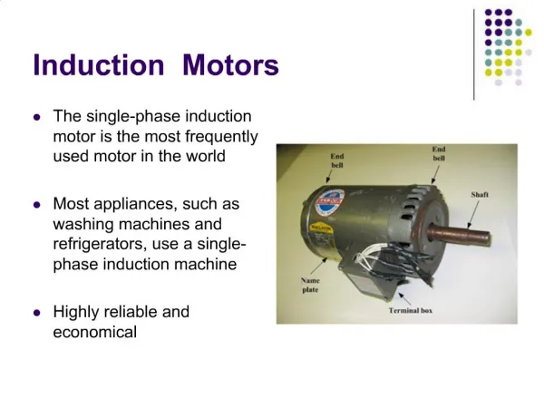
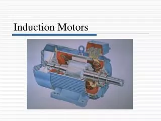
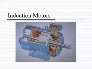
Chapter 18 Single-Phase Induction Motors. Construction of a single-phase induction motor. Single-phase induction motors are very similar to 3-phase induction motors. They are composed of a squirrel-cage rotor (identical to that in a 3-phase motor) and a stator.

E N D
Chapter 18 Single-Phase Induction Motors Electro Mechanical System
Construction of a single-phase induction motor • Single-phase induction motors are very similar to 3-phase induction motors. They are composed of a squirrel-cage rotor (identical to that in a 3-phase motor) and a stator. • The stator carries a main winding, which creates a set of N, S poles. It also carries a smaller auxiliary winding that only operates during the brief period when the motor starts up. • The auxiliary winding has the same number of poles as the main winding has. Electro Mechanical System
Construction of a single-phase induction motor • The steps in winding a 4-pole, 36-slots stator. Starting with the laminated iron stator, paper insulators or slot liners inserted. • Main winding is laid in the slots; Next, the auxiliary winding is embedded so that its poles straddle those of the main winding. Electro Mechanical System
Construction • Each pole of the main winding consists of a group of four concentric coils, connected in series as shown below. • Adjacent poles are connected so as to produce alternate N, S polarities. The empty slot in the center of each pole and the partially filled slots are used for auxiliary winding. Electro Mechanical System
Magnetomotive force distribution • In order to optimize the efficiency, the magnetomotive force produced by each stator pole must be distributed sinusoidally. • That is the reason for using the special number of turns (l0, 20, 25, and 30) on the four concentric coils. • Let us examine the mmf created by one of the four poles when the concentric coils carry a peak current of, say, 2 amperes. • For example, the 25-turn coil in slots 2 and 8, produces an mmf of 25 X 2 = 50 amperes between these slots. • the 10-turn coil in slots 4 and 6 produces between these slots an mmf of 20 A. Electro Mechanical System
Magnetomotive force distribution Following table shows mmf distribution. • The distribution of these mmfs is illustrated. Total mmf produced in the middle of the pole is 60 + 50 + 40 + 20 = 170A & it drops off in steps on either side of center. • A smooth mmf having a perfectly sinusoidal distribution is shown. • Unlike 3-phase, the mmf of single phase does not rotate and remains fixed, but amplitude varies sinusoidally in time. Electro Mechanical System
Torque-speed characteristics • Suppose the rotor is locked in a 2-pole single-phase induction motor. If an ac voltage is applied to the stator. • The resulting current Is produces an ac flux s. The flux alternates back and forth but, unlike the flux in a 3-phase stator, no revolving field is produced. • The flux induces an ac voltage in the stationary rotor which, in turn, creates large ac rotor currents. • In effect, the rotor behaves like the short-circuited secondary of a transformer; consequently, the motor has no tendency to start by itself. Electro Mechanical System
Torque-speed characteristics • However, if we spin the rotor in one direction or the other, it will continue to rotate in the direction of spin. • As a matter of fact, the rotor quickly accelerates until it reaches a speed slightly below synchronous speed. • The acceleration indicates that the motor develops a positive torque as soon as it begins to turn. • Following diagram shows the typical torque-speed curve when the main winding is excited. Although the starting torque is zero, the motor develops a powerful torque as it approaches synchronous speed. Electro Mechanical System
Principle of operation • The principle of operation of a single-phase induction motor is complex, and may be explained by the cross-field theory. • As soon as the rotor begins to turn, a speed emf E is induced in the rotor conductors as they cut the stator flux s. • This voltage increases as the rotor speed increases. It causes currents Ir. to flow in the rotor bars facing the stator poles. These currents produce an ac flux r. Which acts at right angles to the stator flux s. Electro Mechanical System
Principle of operation • r does not reach its maximum value at the same time as s. In effect, r lags 90° behind s, due to the inductance of the rotor. • Combined action of s and r produces a revolving magnetic field, similar to a 3-phase motor. • The value of r increases with increasing speed, almost equal to s at synchronous speed. Electro Mechanical System
Principle of operation • The diagrams gives a snapshot of the currents and fluxes created respectively by the rotor and stator, at successive intervals of time. • We assume that the motor is running far below synchronous speed, and so r is much smaller than s. By observing the flux in the successive pictures, it is obvious that the combination of s and r produces a revolving field. • The flux is strong horizontally and relatively weak vertically. Thus, the field strength at low speed follows the elliptic pattern shown . Electro Mechanical System
Synchronous speed • Like 3-phase motor; synchronous speed of single phase motor is given by: • ns = 120 f / p • where: • ns = synchronous speed [rpm] • f = frequency of the source [Hz] • p = number of poles • Motor turns at slightly less than synchronous speed • At full load slip is 3% to 5% for fractional horse power motor • Example: • Calculate the speed of 4-pole single phase motor. If slip at full load is 3.4% . Line frequency is 60Hz • ns = 120 f / p = (120 x 60)/4 = 1800 rpm • Speed n is given by: s = (ns – n)/ns • 0.034 = (1800 – n)/1800 • n = 1793 rpm Electro Mechanical System
Making a Motor • http://sci-toys.com/scitoys/scitoys/electro/electro.html#single • http://sci-toys.com/scitoys/scitoys/electro/electro2.html#double • http://sci-toys.com/scitoys/scitoys/electro/electro3.html#two_coil Electro Mechanical System