Download
1 / 46
510 likes | 2.54k Vues
Three-phase induction machines are the most robust and widely used motors in industrial applications. Both stator and rotor windings utilize alternating currents, with the stator energized directly while the rotor is powered through induction. This chapter explores the construction principles, focusing on the lamination in stator and rotor, the rotating magnetic fields, and the equivalent circuit models for performance prediction. It covers applications across various sectors, from home appliances to large industrial motors, detailing operations, efficiency calculations, and test methodologies. ###

E N D
Chapter 4. Three-phase Induction Machines
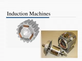
Introduction • The induction machine is the most rugged and the most widely used machine in industry. • Both stator and rotor winding carry alternating currents. • The alternating current (ac) is supplied to the stator winding directly and to the rotor winding by induction – hence the name induction machine. • Application (1-phase): washing machines, ceiling fans, refrigerators, blenders, juice mixers, stereo turntables, etc. • 2-phase induction motors are used primarily as servomotors in a control system. • Application 3-phase: pumps, fans, compressors, paper mills, textile mills, etc.
Construction • Unlike dc machines, induction machines have a uniform air gap. • The stator is composed of laminations of high-grade sheet steel. A three-phase winding is put in slots cut on the inner surface of the stator frame. • The rotor also consists of laminated ferromagnetic material, with slots cut on the outer surface.
Slip ring Wound rotor
Construction Cross-sectional view Y-connected stator -connected stator • The three-phase winding are displaced from each other by 120 electrical degrees in space • Current flows in a phase coil produce a sinusoidally distributed mmf wave centered on the axis of the coil. • Alternating current in each coil produces a pulsating mmf wave. • Mmf waves are displaced by 120 degrees in space from each other. • Resultant mmf wave is rotating along the air gap with constant peak.
Induction Motor Operation RMF – rotating magnetic field
Rotating Magnetic Field – consider 2-pole machine • Three phase stator winding, aa’, bb’ and cc’ displaced by 120o. • Mmf (pulsating) in space at various instants due to a.c current in coil aa’ • Instantaneous 3 phase current
a. Graphical Method – Resultant mmf (magnitude and direction) Resultant mmf Mmf phase a at t = t0= t4
Graphical Method Constant amplitude, move around the air gap n = synchronous speed f = f1= supply freq., p = no of poles rpm
b. Analytical Method Motion of the resultant mmf N = effective number of turns ia= current in phase ‘a’
Induced Voltages A where r = radius of the stator; = axial length of stator
Induced Voltages V per phase
At Standstill operation • E1 = 4.44f1N1pKw1 • E2 = 4.44f2N2pKw2 ; f1 = f2 E2 = 4.44f1N2pKw2
Running Operation at slip s * E2 – induced rotor voltage at standstill
Example 1 • A three-phase, 100 hp, 460 V, four-pole, 60 Hz induction machine delivers rated output power at a slip of 0.05. Determine the (a) Synchronous speed and motor speed. (b) Speed of the rotating air gap field. (c) Frequency of the rotor circuit. (d) Slip frequency (in rpm). (e) Speed of the rotor field relative to the (i) rotor structure (ii) stator structure (iii) stator rotating field (f) Rotor induced voltage at the operating speed, if the stator-to-rotor turns ratio is 1:0.5 Pg 219: 1800 &1710rpm, 1800rpm, 3 Hz, 90 rpm, (90rpm, 1800rpm, 0rpm), 6.64 V/ph) Sol_pg21
Equivalent Circuit Model • To study and predict the performance of the induction machine
Equivalent Circuit Model Stator voltage equation: V1 = R1 I1 + j(2f)LlI1 + Eag; Eag – air gap voltage or back e.m.f Eag = E1 = k f1ag Rotor voltage equation: E2 = R2 I2 + js(2f)Ll2 E2 = k f2ag = k sf1ag = sE1 E2 – induced emf in rotor circuit ; E1=R2/sI2+j2fLI2 Induction Motor Drives SEE4433 Dr Zainal / Dr Awang
Equivalent Circuit Model sE2 – rotor voltage at standstill
Equivalent Circuit Model This model is not convenient to use to predict circuit performance
Example 2 • A three-phase, 15 hp, 460 V, four-pole, 60 Hz, 1728 rpm induction motor delivers full output power to a load connected to its shaft. The windage and friction loss of the motor is 750 W. Determine the (a) mechanical power (b) air gap power (c) rotor copper loss. Pg 226: 11940 W, 12437.5 W, 497.5 W Sol_pg29
Equivalent Circuit Model Assume small volt drop across R1 and X1 – ease computation of I and I2’, V1 = E1 Due to machine air gap, Iis high- 30-50% of full –load current, X1 is high, core loss (Rc) is lumped into the mechanical losses
Equivalent Circuit Model For simplification, replace V1, R1,X1, Xm with Vth, Rth, Xth ( at terminal Pag) R12<<(X1+Xm)2 X1 << Xm
Equivalent Circuit Parameters Rc, Xm, R1, X1, X2, R2
No-Load Test • The parameters of the equivalent circuit, Rc, Xm, R1, X1, X2, and R2 can be determined from the results of a no-load test, a blocked-rotor test and from measurement of the dc resistance of the stator winding. • The no-load test, like the open circuit test on a transformer, gives information about exciting current and rotational losses. • This test is performed by applying balanced polyphase voltages (415V) to the stator windings at the rated frequency(50Hz). • The rotor is kept uncoupled from any mechanical load.
R1 X1 I1 Xm
Blocked-Rotor Test • The blocked-rotor test, like the short-circuit test on a transformer, gives information about leakage impedances. • In this test the rotor is blocked so that the motor cannot rotate, and balanced polyphase voltages are applied to the stator terminal ( increases voltage until stator current reaches its rated value). • The blocked-rotor test should be performed under the same conditions of rotor current and frequency that will prevail in the normal operating conditions. • The IEEE recommends a frequency of 25% of the rated frequency for the blocked-rotor test. However, for normal motors of less than 20 hp rating, the effects of frequency are negligible and the blocked-rotor test can be performed directly at the rated frequency
R1 X1 X2 R2
Equivalent Circuit Parameters • Measurement of average dc resistance per stator phase : R1 • No load test : VNL INL PNL • Blocked-rotor test: VBL INL PNL
Example 3 • The following test results are obtained from a three-phase, 60 hp, 2200 V, six-pole, 60 Hz squirrel-cage induction motor. • No-load test: supply frequency = 60 HZ line voltage = 2200 V line current = 4.5 A input power = 1600 W • Blocked-rotor test: frequency = 15 Hz line voltage = 270 V line current = 25 A input power = 9000 W • Average DC resistance per stator phase: R1 = 2.8 ohm (a) Determine the no-load rotational loss. (b) Determine the parameters of the IEEE-recommended equivalent circuit. (c) Determine the parameters (Vth, Rth, Xth) for the thevenin equivalent circuit. Pg: 230: 1429.9 W Sol_pg38(IM)
Performance calculation using SPEC Induction Motor Drives SEE4433 Dr Zainal / Dr Awang
Example A single phase equivalent circuit of a 6-pole SCIM that operates from a 220 V line voltage at 60 Hz is given below. Calculate the stator current, input power factor, output power, torque and efficiency at a slip of 2.5%. The fixed winding and friction losses is 350 W. Neglect the core loss. Also calculate the starting current. Solution
Example The following results were obtained on a 3 phase, star connected stator, 75 kW, 3.3 kV, 6-pole, 50 Hz squirrel-cage induction motor. No-load (NL) test: Rated frequency, 50 Hz VNL = 3.3 kV (line), INL = 5A, PNL = 2500 W Blocked-rotor (BR) test: Frequency 50 Hz VBR = 400 V (line), IBR = 27 A, PBR = 15000 W DC test on stator resistance per phase = 3.75. i) Determine the parameters of the IEEE recommended equivalentcircuit. ii) Find the parameters of the Thevenin equivalent circuit as seen from the rotor circuit. iii) For a slip of 4%, calculate the stator current, power factor and efficiency of the motor. Sol_pg46