Three Phase Induction Motors
290 likes | 611 Vues
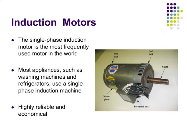
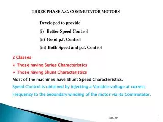
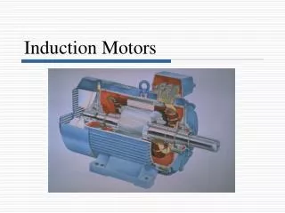
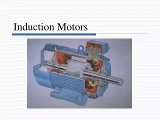
Three Phase Induction Motors. Dept of E & E, MIT Manipal. L4 – 01. Lecture 4. Introduction Power Stages Additional Exercises Induction Motor Starting Considerations Starting Methods Summary. Power Stages. Rotor Copper Loss. Rotor Losses. Stator Copper Loss. Stator Losses.

Three Phase Induction Motors
E N D
Presentation Transcript
Dept of E & E, MIT Manipal L4 – 01 Lecture 4 • Introduction • Power Stages • Additional Exercises • Induction Motor Starting Considerations • Starting Methods • Summary
Power Stages Rotor Copper Loss Rotor Losses Stator Copper Loss Stator Losses Other Losses Core Loss Friction & Windage Loss Dept of E & E, MIT Manipal L4 – 03 Stator Input Stator Output (Rotor Input) Gross Power Output Net Output Stator Input = Motor Input (PIN) Stator Losses = Stator Copper Loss (PSCU) + Core Loss (PCO) Stator Output = Stator Input - Stator Losses Rotor Input = Stator Output Rotor Losses = Rotor Copper Loss (PRCU) Gross Power Output (Pg) = Rotor Input - Rotor Losses Net Power Output (PO) = Gross Power Output (Pg) – Friction & Windage Losses (PFWL)
Dept of E & E, MIT Manipal L4 – 02 Relationship between Rotor Quantities • Pg = Gross output, Prcu = Rotor copper loss, P2 = Rotor input Power transferred from stator to rotor Power developed by the rotor Rotor copper loss, Prcu = P2 - Pg Rotor input (P2) = Rotor copper loss (Prcu) + Gross output (Pg) FromPrcu = sP2&Pg = (1-s)P2
Dept of E & E, MIT Manipal L4 – 04 Lecture 4 Exercise [1] A A 3, 50 Hz, 4 pole star connected induction motor on full load develops a useful torque of 300 Nm. If the rotor emf is 120 cycles per minute and torque lost in friction is 50 Nm, determine (a) slip (b) operating speed (c) net power output (d) gross torque (e) power lost due to friction & windage (f) gross power output (g) total power input if total losses are 10 kW (h) efficiency [2] A 3, 50 Hz, 36 kW, 4 pole induction motor has a full load efficiency of 84 %. The friction & windage losses are one-third of no load losses and rotor copper losses equal the iron loss at full load. Determine (a) Total Losses (b) Stator Core Loss (c) Rotor Copper Loss (d) Friction & Windage Loss (e) Gross Power Output (f) Rotor Input
Induction Motor Starting Considerations X2 E2 I2r Dept of E & E, MIT Manipal L4 – 05 At starting • Higher magnitude of rotor induced emf • Short circuited rotor conductors, Higher rotor current magnitude • Higher magnitude of Stator current, 5 to 8 times rated value • Damages the motor windings • Large voltage drop in supply system To limit the larger starting current to a safe value, we need a STARTER
Dept of E & E, MIT Manipal L4 – 06 Starting Methods • Direct Online Starter (DOL) • Star-Delta Starter • Auto transformer starter • Rotor resistance starter (Slip ring Type only)
Star - Delta Starter Start Position Star Connection A1 A1 A1 A1 A2 A2 A2 A2 B2 B2 B2 B2 B1 B1 B1 B1 Run Position Delta Connection C2 C2 C2 C2 C1 C1 C1 C1 Run Position Dept of E & E, MIT Manipal L4 – 07
Star - Delta Starter : Salient Points Dept of E & E, MIT Manipal L4 – 08 • At Starting • Star connected Stator windings • Applied Phase voltage reduced by 3 times the line voltage value • Starting current reduced by 3 times the DOL current value • Starting Torque reduced by 3 times • At near about rated speed • Switch changed over to RUN position, delta connected windings • Full line voltage applied across all 3 phases
Dept of E & E, MIT Manipal L4 – 09 Lecture 4 Summary • Relationship between rotor quantities • Power Stages • Stator Input, Stator Losses (mainly core loss), Stator output • Rotor Input, Rotor Losses (mainly copper loss), Rotor Output • Necessity of Starter for starting 3Induction Motors • Higher current magnitude, Winding Damage, Supply System Drop • Star Delta Starter • Star Starting with reduced voltage • Delta Running with full voltage