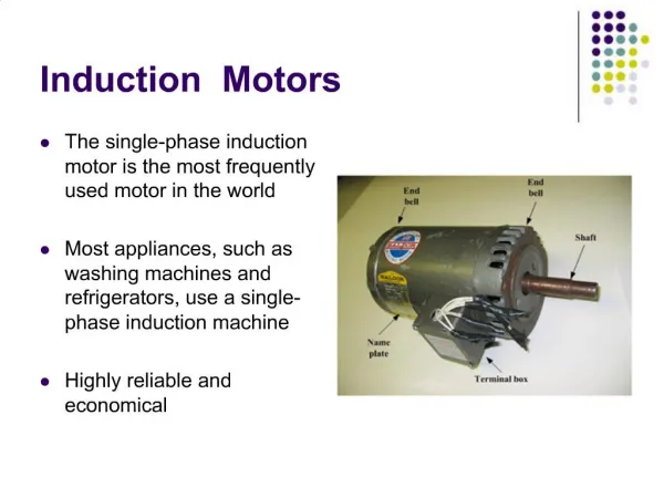
INDUCTION MOTORS 1
INDUCTION MOTORS 1. ROTOR CIRCUIT MODEL. The rotor current : I R = E R / [R R +jX R ] (1) I R =E R / [R R +js X R0 ] or I R =E R0 / [R R /s +j X R0 ] (2)

INDUCTION MOTORS 1
E N D
Presentation Transcript
ROTOR CIRCUIT MODEL • The rotor current: IR = ER/ [RR+jXR] (1) • IR=ER/ [RR+js XR0] or IR=ER0 / [RR /s +j XR0] (2) • Note:from last equation, can treat rotor effects due to varying rotor speedas caused by a varying impedance supplied from a constant voltage source ER0 • Equivalent rotor impedance from this point of view: ZR, eq = RR / s + jXR0 (3) rotor equivalent circuit using this convention shown next
ROTOR CIRCUIT MODEL • Rotor voltage is ER0 constant& rotor impedance ZR,eqcontains effects of varying slip
ROTOR CIRCUIT MODEL • Plot of current flow in rotorfrom equations: (1) & (2)shown below:
FINAL EQUIVALENT CIRCUIT • Note:at very low slips resistive term RR/s>>XR0 rotor resistance predominates & rotor current varies linearly with slip • at high slips, XR0 much larger than RR/s& rotor current approaches steady-state valueas slip becomes very large • To develop a single, per-phase, equivalent circuit for induction motor should refer to rotor part of model over stator side • Rotor circuit model, referred to stator side (shown in last equivalent circuit of rotor) in which effect of speed variation is concentrated in impedance term
FINAL EQUIVALENT CIRCUIT • Reminding: that in an ordinary transformer, voltages, currents and impedances on secondary sideof device can be referred to primary sideby means of turns ratio of transformer • Vp=V’s=a Vs • Ip=I’s=Is / a • Z’s = a^2 Zs • Same sort of transformation employed for induction motor’s rotor circuit • If the effective turns ratio of induction motor = aeff The transformed voltages are: E1=E’R=aeff ER0 • and rotor current is :I2=IR / aeff • And rotor impedance become:Z2 =aeff^2 (RR/ s +j XR0)
FINAL EQUIVALENT CIRCUIT • If the following definitions employed: R2 = aeff^2 RR X2 =aeff^2 XR0 • the equivalent circuit of induction motor is shown as below: (per-phase equivalent circuit)
FINAL EQUIVALENT CIRCUIT • Rotor resistance RR & locked-rotor reactance XR0are difficult or impossible to determinedirectly on cage rotors& effective turns ratio aeff also difficult to determine for cage rotors • fortunately,can make measurements that directly providereferred resistanceand reactance R2 & X2 , (though RR, XR0 and aeff not known separately) • measurement of these parameters covered later
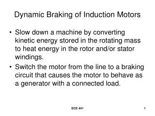
POWER & TORQUE IN INDUCTION MOTORS-LOSSES • since induction motoris a singly excited machine,its power & torque relationships is different from sync. machines • Losses & power-flow Diagram • the input is electric power and the output mechanical power (while rotor windings are short circuited) • As shown in power flow Figure (next), Pin is in form of 3 phase electric voltages & currents • 1st losses is stator winding losses I^2 R=PSCL • 2nd Hysteresis & Eddy currents loss in stator Pcore • Power remained at this point transferred to rotor through air gap: is called air-gap power PAG
POWER & TORQUE IN INDUCTION MOTORS-LOSSES • Part of power transferred to rotor lost as : I^2R=PRCL& rest converted from electrical to mechanical form Pconv, friction & windage losses PF&W & stray losses Pmisc subtracted Pout
POWER & TORQUE IN INDUCTION MOTORS-LOSSES • Note:in practice core loss is partially related to stator and partially to rotor, however since induction motor operates at a speed near synchronous speed, relative motion of magnetic field over rotor surface is quite low (frequency of induced voltage = s fe)& rotor core losses are very tiny • These losses in induction motor equivalent circuit represented by a resistor RC (or GC) , • If core losses are given as a number (X Watts)often lumped with mechanical losses& subtracted at point on diagram where mechanical losses are located
POWER & TORQUE IN INDUCTION MOTORS-LOSSES • The higher the speed of an induction motor,the higher its friction, windage, and stray losses,while the lower the core lossessometimes these 3 categories of losses are lumped together and calledrotational losses • Since component losses of rotational losseschange in opposite directions with a change in speed,total rotational losses of a motor often considered constant • EXAMPLE : A 480, 60 Hz, 50 hp, 3 phase induction motor is drawing 60 A at 0.85 PF lagging The stator copper losses are 2 kW, and rotor copper losses are 700 W, friction & windage losses are 600 W, core losses 1800 W, and stray losses negligible. Find: • (a) PAG (b) Pconv (c) Pout (d) efficieny of motor
POWER & TORQUE IN INDUCTION MOTORS-LOSSES EXAMPLE • (a) PAG=Pin-PSCL – Pcore Pin=√3 VT IL=√3 (480) (60) (0.85)=42.4 kW PAG=42.4-2-1.8= 38.6 kW • (b) Pconv=PAG-PRCL=38.6-700/1000=37.9 kW • (c) Pout=Pconv-PF&W-Pmisc=37.9-600/1000-0 = 37.3 kW = 37.3/ 0.746 = 50 hp • (d) efficiency of motor η =Pout/Pin x 100 % =88 %
POWER & TORQUE IN INDUCTION MOTORS • Employing the equivalent circuit, power & torque equations can be derived • Input current I1= Vφ/ Zeq = R1 + jX1 + 1/{[GC-jBM +1/[R2/s +jX2]}
POWER & TORQUE IN INDUCTION MOTORS stator copper losses, core losses and rotor copper losses can be found • stator copper losses (3 phase)=PSCL= 3 I1^2 R1 • core losses Pcore = 3 E1^2 GC PAG=Pin-PSCL-Pcore • only element in equ. cct. where air gap power can be consumed is resistor R2/s , & air gap power can also be given: PAG=3 I2^2 R2/s (1) • Actual resistive losses in rotor circuit: PRCL=3 I2^2R2 (2) • Pconv=PAG- PRCL=3I2^2R2/s-3I2^2R2 = 3I2^2 R2 (1/s-1) Pconv= 3I2^2 R2 (1-s)/s
POWER & TORQUE IN INDUCTION MOTORS • Note: • from equations (1) & (2) rotor copper losses = air gap power x slip • The lower the slip the lower the lower rotor losses • And if rotor is stationary s=1 & air gap power is entirely consumed in rotor, this is consistent with the fact that output power in this case would be zero since ωm=0, Pout=Tload ωm=0 Pconv=PAG-PRCL=PAG-sPAG=(1-s)PAG(3) • If friction & windage losses and stray losses are known, output power Pout=Pconv-PF&W- Pmisc
POWER & TORQUE IN INDUCTION MOTORS • Induced torque Tindas : torque generated by internal electric to mechanical powerconversion • It differs from available torqueby amount equal to friction & windage torques in machine • Tind=Pconv/ωm also calleddeveloped torque of machine • Substituting for Pconv from (3) & forωm, (1-s) ωsync Tind= (1-s)PAG/ [(1-s)ωsync]= PAG/ωsync (4) So (4) express induced torque in terms of air-gap power & sync. Speed which is constant PAG yields Tind
POWER & TORQUE IN INDUCTION MOTORS • SEPARATION of PRCL & Pconv in induction motor Eq. cct. • Part of power coming across air gapconsumed in rotor copper losses,& the other part converted to mechanical power to drive motor shaft • it is possible to separate these two different uses of air-gap power& present them separately in the equivalent circuit • Equation (1) is an expression for total air-gap power, while (2) gives actual rotor losses, the difference between these two is Pconv & must be consumed in an equivalent resistor • Rconv=R2/s-R2 = R2(1/s-1) =R2 (1-s)/s
POWER & TORQUE IN INDUCTION MOTORS • The per-phase equivalent circuit with rotor copper losses& power converted to mech. form separated into distinct elementsshown below:
POWER & TORQUE IN INDUCTION MOTORS – TORQUE EXAMPLE • a 460 V, 60 Hz, 25 hp, 4 pole, Y connected induction motor has following impedances in Ω /phase referred to stator circuit: R1=0.641 Ω R2=0.332 Ω X1 = 1.106 Ω X2 = 0.464 Ω XM=26.3 Ω total rotational losses are 1100 W, & assumed to be constant core loss is lumped in with rotational losses. For rotor slip of 2.2 % at rated voltage & rated frequency,find: • Speed (b) stator current (c) P.F. (d) Pconv & Pout (e) Tind & Tload (f) Efficiency
POWER & TORQUE IN INDUCTION MOTORS – TORQUE EXAMPLE • (a) nsync=120 fe/p=120 x60/4=1800 r/min ωsync=1800 x 2π x 1/60= 188.5 rad/s rotor’s mechanical shaft speed: nm=(1-s) nsync=(1-0.022) x 1800=1760 r/min ωm= (1-s) ωsync= (1-0.022) x 188.5= 184.4 rad/s • (b) to find stator current, consider eq. impedance of cct.Then combine referred rotor impedance in parallel with magnetization branch, and add stator impedance to the combination in series • The referred rotor impedance is : Z2= R2/s + j X2 =0.332 / 0.022 + j0.464 =15.09+j0.464=15.1/_ 1.76◦ Ω combined magnetization plus rotor impedance is: Zf = 1/[1/(jXM) + 1/Z2] = 1/ [-j0.038 + 0.0662/_ -1.76◦]= 1/[0.0773/_ -31.1◦]=12.94/_31.1 ◦
POWER & TORQUE IN INDUCTION MOTORS – TORQUE EXAMPLE • Total impedance : Ztot= Zstat+Zf = = 0.641+j1.106+12.94/_31.1◦ Ω = 11.72 + j7.79 =14.07 /_33.6◦ Ω • Resulting stator current: I1=Vφ/Ztot = 206/_0◦ / 14.07 /_33.6 = 18.88/_-3.6 A
POWER & TORQUE IN INDUCTION MOTORS – TORQUE EXAMPLE • (c) motor power factor: PF=cos 33.6 = 0.833 lagging • (d) Input power of motor: Pin=√3 VT VL cos θ=√3 x 460 x 18.88 x 0.833= 12530 W • PSCL=3 (18.88)^2 (0.641)=685 W • air-gap power :PAG=Pin-PSCL=12530-685=11845 Wand the power converted is: • Pconv=(1-s)PAG =(1-0.022)(11845) =11585 W • Pout=Pconv-Prot=11585-1100=10485 W=14.1 hp
POWER & TORQUE IN INDUCTION MOTORS – TORQUE EXAMPLE • (e) induced torque is: Tind=PAG/ ωsync = 11845 / 188.5 =62.8 N.m • output torque: Tload=Pout/ωm= 10485/184.4=56.9 N.m • (f) motor’s efficiency: η= Pout/ Pin x 100% =10485/12530 x 100% = 83.7 %
INDUCTION MOTOR TORQUE CHARACTERISTIC • How does its torque change as load changes? • How much torque can supply at starting conditions?how much does the speed of induction motor drop as its shaft load increases? • it is necessary to understand the relationship among motor’s torque, speed, and power • the torque-speed characteristic examinedfirst from physical viewpoint of motor’s magnetic field& then a general equation for torque as function of slip derived
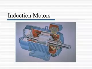
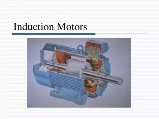
INDUCTION MOTOR TORQUE CHARACTERISTIC • Induced Torque from a Physical Viewpoint • Figure shows a cage rotor of an induction motor • Initially operating at no load & nearly sync. speed
INDUCTION MOTOR TORQUE CHARACTERISTIC • Net magnetic field Bnet produced by magnetization current IM flowing in motor’s equivalent circuit • Magnitude of IM and Bnet directly proportional to E1 • If E1 constant, then Bnet constant • In practice E1 varies as load changes, because stator impedance R1 and X1 cause varying voltage drops with varying load • However, these drops in stator winding is relatively small so E1 ( hence IM & Bnet) approximately constant with changes in load • In Fig (a) motor is at no load, its slip is very small & therefore relative motion between rotor and magnetic field is very small & rotor frequency also very small
INDUCTION MOTOR TORQUE CHARACTERISTIC • Consequently ER induced in rotor is very small, and IR would be small • So frequency is very small, reactance of rotor is nearly zero, and maximum rotor current IR is almost in phase with rotor voltage ER • Rotor current produces a small BR at an angle just slightly greater than 90◦ behind Bnet • Note:stator current must be quite large even at no load, since it supply most of Bnet • That is why induction motors have large no load currents compared to other types of machines
INDUCTION MOTOR TORQUE CHARACTERISTIC • The induced torque, which keeps rotor running is given by: Tind = k BR x Bnet or Tind=k BR Bnet sinδ • Since BR is very small, Tind also quite small, enough just to overcome motor’s rotational losses • suppose motor is loaded (in Fig (b)) as load increase, motor slip increase, and rotor speed falls. Since rotor speed decreased, more relative motion exist between rotor & stator magnetic fields in machine • Greater relative motionproduces a stronger rotor voltage ERwhich in turn produces a larger rotor current IR
INDUCTION MOTOR TORQUE CHARACTERISTIC • Consequently BR also increases, however angle of rotor current & BR changes as well • Since rotor slip get larger, rotor frequency increases fr=sfe and rotor reactance increases (ω LR) • Rotor current now lags further behind rotor voltage (as shown) & BR shift with current • Fig b, shows motor operating at a fairly high load • Note:at this situation, rotor current increased and δ increased • Increase in BR tends to increase torque, while increase in δ tends to decrease the torque (δ>90) • However since the effect of first is higher than the second in overall induced torque increasedwith load
INDUCTION MOTOR TORQUE CHARACTERISTIC • Using: Tind=k BR Bnet sinδ derive output torque-versus-speed characteristic of induction motor • Each term in above equation considered separately to derive overall machine behavior • Individual terms are: 1. BR directly proportional to current flowing in rotor, as long as rotor is unsaturated Current flow in rotor increases with increasing slip (decreasing speed) it is plotted 2- Bnet magnetic field in motor is proportional to E1 & therefore approximately constant (E1 actually decreases with increasing current flow) this effect small compared to the other two & ignored in drawing 3- sinδ : δ is just equal to P.F. angle of rotor plus 90◦ δ=θR+90 And sinδ=sin(θR+90)=cos θR which is P.F. of rotor
INDUCTION MOTOR TORQUE CHARACTERISTIC • Rotor P.F. angle can be determined as follows: θR =atan XR/RR = atan sXR0 / RR PFR = cos θR PFR=cos(atan sXR0/RR) • plot of rotor P.F. versus speed shown in fig (c) • Since induced torqueis proportionalto product of these 3 terms,torque-speed characteristic can be constructed from graphical multiplication of 3 previous plots Figs (a,b,c) and shown in fig (d)
INDUCTION MOTOR TORQUE CHARACTERISTIC • Development of induction motor torque –speed
INDUCTION MOTOR TORQUE CHARACTERISTIC • This characteristic curve can be divided into three regions • 1st region:is low-slip regionin which motor slip increases approximately linearlywith increase load & rotor mechanical speed decreases approximately linearly with load • In this regionrotor reactance is negligible, so rotor PF is approximately unity, while rotor current increases linearly with slip • The entire normal steady-state operating range of an induction motor is included in this linear low-slip region
INDUCTION MOTOR TORQUE CHARACTERISTIC • 2nd region on curve called moderate-slip region • Inmoderate-slip regionrotor frequencyis higher than before,& rotor reactance is on the same order of magnitude as rotor resistance - In this region rotor current, no longer increases as rapidly as beforeand the P.F. starts to drop - peak torque(pullout torque)of motor occurs at point where, for an incremental increase in load, increase in rotor current is exactly balanced by decrease in rotor P.F.
INDUCTION MOTOR TORQUE CHARACTERISTIC • 3rd region on curve is called high-slip region • In high-slip region, induced torque actually decreases with increased load, since the increase in rotor current is completelyovershadowed by decrease in rotor P.F. • For a typical induction motor, pullout torque is 200 to 250 % of rated full-load torque • And starting torque (at zero speed) is about 150% of full-load torque • Unlike synchronous motor, induction motor can start with a full-load attached to its shaft
INDUCTION MOTOR INDUCED-TORQUE EQUATION • Equiv. circuit of induction motor & its power flow diagram used to derive a relation for induced torque versus speed • Tind=Pconv/ωm or Tind=PAG/ωsync • Latter useful, since ωsync is constant (for fe & and a number of poles)so from PAG Tind • The PAG is equal to power absorbed by resistor R2/s , how can this power be determined?
INDUCTION MOTOR INDUCED-TORQUE EQUATION • In this figure the air-gap power supplied to one phase is: PAG,1φ=I2^2 R2/s • for 3 phase: PAG=3I2^2 R2/s
INDUCTION MOTOR INDUCED-TORQUE EQUATION • If I2 can be determined, air-gap power & induced torque are known • easiest way to determine Thevenin equivalent of the portion of circuit to left of arrow E1in eq. cct. figure VTH= Vφ ZM/ [ZM+Z1] = Vφ j XM / [R1+jX1+jXM] • Magnitude of thevenin voltage: VTH= Vφ XM / √[R1^2+(X1+XM)^2] VTH≈ Vφ XM / [X1+XM], ZTH = Z1ZM /[Z1+ZM] ZTH=RTH+jXTH = jXM(R1+jX1)/[R1+j(X1+XM)]
INDUCTION MOTOR INDUCED-TORQUE EQUATION • Thevenin equivalent voltage of induction motor