Introduction to Induction Machines: Construction and Operation
540 likes | 634 Vues
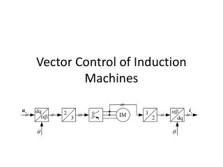
Discover the construction, principle of operation, and rotor variations of induction machines. Learn about rotor resistance, slip, and frequency control in these widely used industrial motors.

Introduction to Induction Machines: Construction and Operation
E N D
Presentation Transcript
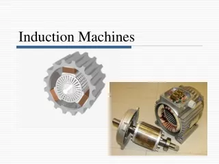
Introduction • Most industrial motors are squirrel cage induction machines because of their simple and robust construction, low cost, minimal maintenance, and inherent overload protection. • However, induction generators are much less widely used because the drive speed, electrical frequency, voltage, load, and equivalent terminal capacitance must be juggled to provide both the reactive excitation power to the machine and the varying real power to the load. • This type of generator is not widely used outside the wind turbine industry, and in small hydropower units
Construction • An induction machine has two main parts • a stationary stator • consisting of a steel frame that supports a hollow, cylindrical core • core, constructed from stacked laminations, having a number of evenly spaced slots, providing the space for the stator winding Stator of IM
Construction • a revolving rotor • composed of punched laminations, stacked to create a series of rotor slots, providing space for the rotor winding • one of two types of rotor windings • conventional 3-phase windings made of insulated wire (wound-rotor) » similar to the winding on the stator • aluminum bus bars shorted together at the ends by two aluminum rings, forming a squirrel-cage shaped circuit (squirrel-cage) • Two basic design types depending on the rotor design • squirrel-cage: conducting bars laid into slots and shorted at both ends by shorting rings. • wound-rotor: complete set of three-phase windings exactly as the stator. Usually Y-connected, the ends of the three rotor wires are connected to 3 slip rings on the rotor shaft. In this way, the rotor circuit is accessible.
Construction Squirrel cage rotor (copper) Wound rotor Notice the slip rings
Construction Slip rings Cutaway in a typical wound-rotor IM. Notice the brushes and the slip rings Brushes
Principle of operation • The stator is usually connected to the grid and, thus, the stator is magnetized • A rotating magnetic field with constant magnitude is produced, rotating with a speed
Principle of operation contd.. • In order to generate power the rotor speed must be slightly above the synchronous speed • The harder the rotor is cranked, the more power will be fed into the electrical grid
The Slip Where s is the slip. Slip is one of the most important variables in the control and operation of induction machines. s = 0 : if the rotor runs at synchronous speed s = 1 : if the rotor is stationary s is –ve : if the rotor runs at a speed above the synchronous speed s is +ve : if the rotor runs at a speed below the synchronous speed
Frequency • The frequency of the voltage induced in the rotor is given by Where fr= the rotor current frequency (Hz) P = number of stator poles n = slip speed (rpm)
Alternative Rotor Constructions • High efficiency at normal operating conditions requires a low rotor resistance. • On the other hand, a high rotor resistance is required to produce a high starting torque and to keep the magnitude of the starting current low and the power factor high. • The wound rotor is one way of meeting the above mentioned need for varying the rotor resistance at different operating conditions. Wound-rotor motors are, however, more expensive than squirrel-cage motors. Effect of the rotor resistance the torque-slip curves.
Double Squirrel-Cage Rotor Construction • Following double squirrel-cage arrangements can also be used to obtained a high value of effective resistance at starting and a low value of the resistance at full-load operation. • It consists of two layers of bars, both short-circuited by end rings. • The upper bars are small in cross-section and have a high resistance. • They are placed near the rotor surface so that the leakage flux sees a path of high reluctance; consequently, they have a low leakage inductance. • The lower bars have a large cross-section, a lower resistance and a high leakage inductance. Double squirrel-cage rotor bars
Double Squirrel-Cage Rotor Construction (cont’d) • At starting, rotor frequency is high and very little current flows through the lower bars; the effective resistance of the rotor is then the high resistance upper bars. • At normal low slip operation, leakage reactances are negligible, and the rotor current flows largely through the low resistance lower bars; the effective rotor resistance is equal to that of the two sets of bars in parallel. Double squirrel-cage rotor bars
Deep-Bar Rotor Construction • The use of deep, narrow rotor bars produces torque-slip characteristics similar to those of a double-cage rotor. • Leakage inductance of the top cross-section of the rotor bar is relatively low; the lower sections have progressively higher leakage inductance. • At starting, due to the high rotor frequency, the current is concentrated towards the top layers of the rotor bar. • At full-load operation, the current distribution becomes uniform and the effective resistance is low. Deep-bar rotor construction
Equivalent Circuit with a Double Cage or Deep Bar Rotor Equivalent circuit of a single- cage induction motor (with one rotor winding). Equivalent circuit of a double- cage induction motor (two rotor windings).
Equivalent Circuit Single Rotor Circuit Representation For system studies, the rotor should be represented by a single rotor circuit whose parameters vary as a function of slip, s.
Modeling Induction Machines In developing the model of induction machines, following aspects will differ from those of synchronous machines: • The d- and q-axis equivalent circuits are identical as the rotor has symmetrical structure. • The rotor speed is not fixed but varies with load. This has an impact on the selection of the d-q reference frame. • There is no excitation source to the rotor windings. Consequently, the dynamics of the rotor circuits are determined by slip. • The current induced in the shorted rotor windings produce a field with the same number of poles as that produced by the stator windings. Rotor windings may therefore be modeled by an equivalent three-phase winding.
Equivalent Circuit • We can rearrange the equivalent circuit as follows Resistance equivalent to mechanical load Actual rotor resistance
Power losses in Induction machines • Copper losses • Copper loss in the stator (PSCL) = I12R1 • Copper loss in the rotor (PRCL) = I22R2 • Core loss (Pcore) • Mechanical power loss due to friction and windage • How this power flow in the motor?
Torque, power and Thevenin’s Theorem Then the power converted to mechanical (Pconv) And the internal mechanical torque (Tconv)
Torque-speed characteristics Typical torque-speed characteristics of induction motor
Maximum torque • Maximum torque occurs when the power transferred to R2/s is maximum. • This condition occurs when R2/s equals the magnitude of the impedance Req + j (Xeq + X2)
Maximum torque • The corresponding maximum torque of an induction motor equals • The slip at maximum torque is directly proportional to the rotor resistance R2 • The maximum torque is independent of R2
Maximum torque • Rotor resistance can be increased by inserting external resistance in the rotor of a wound-rotor induction motor. • The value of the maximum torque remains unaffected but the speed at which it occurs can be controlled.
Maximum torque Effect of rotor resistance on torque-speed characteristic