Download
1 / 24
280 likes | 376 Vues
Explore dynamic phasors for modeling single-phase motors, encompassing performance, point-on-wave, and dynamic phasor models. Learn how to simulate various harmonics and tackle sub-cycle phenomena in positive sequence simulations.

E N D
Dynamic PhasorsSingle Phase Induction Motorspoint-on-wave disturbances Bernie Lesieutre UW-Madison WECC MVWG, January 2018
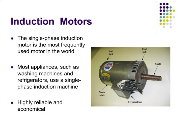
Modeling Need We need single-phase motor models for positive sequence simulations. Three types have been developed as part of load modeling efforts: • Performance model (static) • Dynamic phasor model • Point-on-wave model – detailed, first principles model
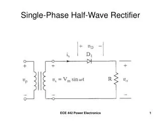
What Are Dynamic Phasors? Start with simple example. Consider the basic RL circuit; given a sinusoidal voltage, solve for sinusoidal current. Given Solve for Direct Substitution yields Tediously solve for
What Are Dynamic Phasors? Transition to phasor notation. Where is our traditional phasor.
What Are Dynamic Phasors? Solve using phasor analysis. Use Direct Substitution yields Trivially solve for current phasor And time domain current:
What Are Dynamic Phasors? Allow phasors to vary slowly in time Use Direct Substitution yields Which can be simulated. N.B. Assumes phasor vary slowly relative underlying frequency. i.e. not intended to capture sub-cycle phenomenon.
What Are Dynamic Phasors? In practice, we can model multiple harmonics using dynamic phasors: So far in our work, we’ve only used 1st harmonics for electrical variables, and 0th harmonic for mechanical. More detail is possible.
Dynamic phasors - example The information is contained in the envelope and phase. The dyanamic phasor model is similar to detailed model, but “averaged” in some sense over a cycle.
Single Phase Compressor Simulation Model Point-on-Wave model in stationary reference frame.
Dynamic phasors - conceptually Represent a waveform as a short-timescale complex Fourier series with time-varying coefficients. offset term fundamental term harmonic terms For the purpose of implementation in a positive sequence simulator, we ignore offset and harmonic terms. What are the implications of this?
Dynamic phasors - conceptually Most of the time we expect the fundamental terms to dominate the characteristic. The offset should be small, and we neglect harmonics. However, we find that this fundamental-terms model does not necessarily represent subcycle phenomena.
Back to dynamic Phasors… How might we represent these effects in a dynamic phasor model? Assuming a voltage-driven model, what should the driving terms look like?
Time-windowed voltage phasors Disturbance at voltage crest Disturbance at voltage zero Analyze this with a one-cycle window, sliding Fourier Transform
Time-windowed voltage phasors Disturbance at voltage crest Disturbance at voltage zero What to do with this information?
Adjustments to simulation/model Issues • We would like to keep the model suitable for positive sequence simulators. • We don’t want to expand it to include additional terms (harmonics), if we don’t have to.
Adjustments to simulation/model Possible approaches to insert braking torque • Direct in torque: for zero-crossing events, apply short braking torque. (how much?) • Direct in voltage: for zero-crossing events, apply short phase angle pulse to applied voltage. Fit the model parameters to match voltage crest data.
Voltage Phase Implementation For zero crossing events, include negative phase angle pulse
Laboratory Tests and Simulations • Air Conditioner Tests at BPA Facility • Test Point-on-Wave Response • Trane Compressor • Dynamic Phasor Simulations with voltage angle pulse. Voltage dip to 30-60%% nominal Recovery voltage at 85% nominal. (lower value to ensure stalling) Find fault duration to result in a stall Voltage ramp test for model fitting.
Fault Regions, Instantaneous Voltage Dip Zero Crossing Peak
Needed Continuing Work • More on accommodating fast transients – possibly adding other harmonic terms to the model • Parameter Fitting • Minor adjustments to reference frame
Zero Crossing, with ramp Instantaneous One cycle ramp