AMCOM MK66
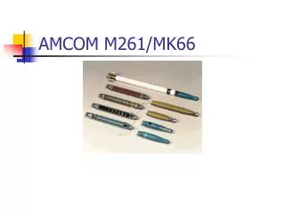
AMCOM MK66. Final Presentation Filiz Genca Ashley Devoto Jeff Kohlhoff Matt Galante Jason Newquist Adrian Lauf Shannon Stonemetz. Project Overview. Development of a precision guidance avionics module for the Hydra 70 rocket missile. M261 MPSM warhead

AMCOM MK66
E N D
Presentation Transcript
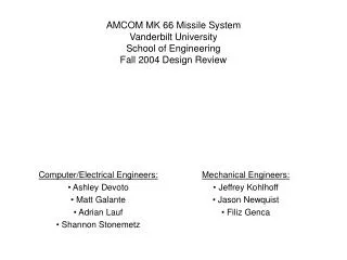
AMCOM MK66 Final Presentation Filiz Genca Ashley Devoto Jeff Kohlhoff Matt Galante Jason Newquist Adrian Lauf Shannon Stonemetz
Project Overview • Development of a precision guidance avionics module for the Hydra 70 rocket missile. • M261 MPSM warhead • M261 19-round launch platform • MK 66 rocket motor • Module will have built in IMU and GPS guidance systems • Module will contain 4 canards actuated by servo motors that will perform flight adjustments • Manufacture a mechanical prototype
Software Block Diagram Parallel Control Roll Compensation Course Plot/ Correction Data Handler IMU Data Processing SW GPS Data Processing SW RMS Control Software Serial I/O Control Routines Servo Lines, Deploy Line RS-232 Devices: (IMU, GPS, RMS)
GPS Interfacing • Outputs raw data (real-time data) • Binary format • Transmission Protocol • 8 bits • 1 stop bit • No parity bit • Output Interval • Can be set to any time between .05 and 999 seconds
IMU Specifications • Honeywell HG1930 Gun-Hard MEMS IMU • RS422 interface • Must be converted to 232 • Synchronous or Asynchronous • Output • Linear Acceleration • Angular acceleration
Correction sequence Differential Calculations Correction determined: -5°, +5°, -5°, +5° Power Conversion -A -B -C -D +A +B +C +D 0 1 0 1 1 0 1 0 -1 1 -1 1 Translation to servo codes Control Logic 1 Back B Servo 4 2 A C D Feedback 3 Servo mapping and line addressing Reference frame applied
Module Shell and Interfaces • Aluminum Construction • 15 inches long • Acme Stub Nose Threads 6 pitch • .5 in deep interference fit into shell • Secured with press fit pull out pins
Frame Subassembly • .25 in aluminum construction • Struts to mount IMU, GPS, CPU, Thermal Battery • .5 in x .5in Mounting bar for canard assembly
Canard • Aluminum construction • Machined from single piece • NACA 0012 Airfoil Shape • Positive stop machined into canard • Hole to receive negative stop
Canard Deployment • Helical torsion spring for deployment • Positive stop machined into mechanism • Spring loaded negative stop
Canard Actuation • Anti backlash gears • Gears mount to tab on assembly • Assembly rotates about nubbin • Nubbin connected to frame mounting bar w/snap ring
Final Demonstration “GPS, IMU, RMS” • Two notebook PCs • One will act as Altera-based processing board • Second will act as GPS, IMU, RMS, providing simulated data • More flexible • Nios Devel. Kit has no readily-useable parallel port RS232 “FPGA Processor board” Servo IEEE 1284 (Parallel)