Chapter 7—packet-switching
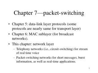
Chapter 7—packet-switching. Chapter 5: data-link layer protocols (some protocols are nearly same for transport layer) Chapter 6: MAC sublayer (for broadcast networks). This chapter: network layer Telephony networks (i.e., circuit-switching) for stream of real time voice

Chapter 7—packet-switching
E N D
Presentation Transcript
Chapter 7—packet-switching • Chapter 5: data-link layer protocols (some protocols are nearly same for transport layer) • Chapter 6: MAC sublayer (for broadcast networks). • This chapter: network layer • Telephony networks (i.e., circuit-switching) for stream of real time voice • Packet-switching networks for short messages, burst information, as well as real-time applications.
Two views of networks • External view: what services provided to transport layer by a network (i.e. network layer) • Need connection setup or not • What QoSs are provided • Services should be independent from underlying networks so that transport layer can run over any networks as long as the networks provide the services • Internal view: • physical topology, • datagram message transfer or virtual circuit information transfer, • addressing and routing, congestion control. • In this chapter, networks indicate systems to transfer information from one end to the other. It is reasonable to consider networks to be network layer here.
Comparisons of two views by examples • Broadcast networks and packet-switched networks • From external view, both networks provides transfer of information between users, not too much different • But from internal view, very different: • A broadcast network (such as LANs) is small, addressing is simple, frame transferred in one hop so no routing is needed • In a packet-switching network, addressing must accommodate large-scale networks and routing is necessary.
What we will discuss • Network services and internal network operations • Physical view of networks, • Datagram and virtual circuit • Routing • Shortest path algorithms • ATM networks • Traffic management and congestion control (if have time)
t1 t0 Transfer of a block of info. VS. a sequence of blocks Network Figure 7.1
Services provided by network layer • Two basic kinds of services • One view: Transfer of a block of information VS. a sequence of blocks • Second view: connectionless VS. connection-oriented. • IP provides connectionless service VS. ATM provides connection-oriented service • Other services such as: • Best-offer connectionless services • Low-delay connectionless service • Connection-oriented reliable stream service • Connection-oriented transfer of packets with delay and bandwidth guarantees • End-to-end argument: • Functions should be placed as close as possible to the application since the application is in best position to determine whether a function is being carried out completely and correctly, • Therefore, network layer should provide minimum functions required to meet application requirements and performance. Leave more functions to upper layers such as transport layer.
protocol stack: network provides minimum required services to transport layer Messages Messages Segments Transport layer Transport layer Network service Network service Network layer Network layer Network layer Network layer End system b End system a Data link layer Data link layer Data link layer Data link layer Physical layer Physical layer Physical layer Physical layer Figure 7.2
Discussion of connectionless vs. connection-oriented Transport layer: connectionless connection-oriented Network layer: connectionless(IP) connection-oriented (ATM) Both connection-oriented and connectionless services in the upper layer can be implemented over a connectionless network (layer) (such as IP), similarly, can be implemented over a connection-oriented network (layer) (such as ATM). In network layer, connectionless service is also called datagram service, connection-oriented service called virtual-circuit service. Thinking: differences (or implications) of connection-oriented in transport layer and in network layer. What the connection between two ends in transport layer means? Which is preferred? From end-to-end argument, connectionless network (IP) is preferred because IP makes intermediate nodes as simple as possible and put the burden on end systems. Moreover, it makes the network grow easily (more scalable). Why ATM which is connection-oriented? Main reason is QoS because connection-oriented network can easily guarantee bandwidth, delay, etc. Detail motivation behind ATM will be discussed later.
Most basic functions of a network (layer) Routing and forwarding. Priority and scheduling (to provide QoS) Congestion control (also in transport layer) Segmentation (to deal with different frame sizes of underlying systems) Alternatively, network (layer) sends error message to let edge system to do segmentation. Addressing 1. to deal with different address formats when interconnecting networks. 2. Hierarchical address for scalability.
Packet network topology --Access multiplexer Access node forwards packets into backbone packet networks. Multiplexer combines multiple bursty flows into one aggregated flow. Network access . . . MUX Node Figure 7.4
Packet network topology --LAN LANs were introduced for sharing of resources in a organization. They are basic building components for Wide Area Networks. (a) (b) LAN LAN 1 Bridge LAN 2 Now nearly every LAN is connected to packet-switching network (the Internet) to share information globally and to make the Internet extremely large. Figure 7.5
Campus network Gateway Organization Servers To internet or wide area network s s Backnone network may be connected by links, LAN, or ATMs. Backbone R R R S Departmental Server S S R R R s s s s s s s s s LANsextended LANs subnetworks (by backbone networks) campus network university network, finally connect to Internet, Servers provide various services. bridges, routers and gateway,… play key-role in networks Figure 7.6
Domain: indicate the routers run the same routing protocols. Interdomain level Border routers Internet service provider Autonomous system or domain Border routers Autonomous systems: included domains under a single administrations LAN level • Various networks are connected through ISP. • Tremendous small office and home (SOHO) users connect to the Internet through ISP, using dynamic IPs. Intradomain level Intradomain and interdomain levels Figure 7.7
National service provider A (a) National service provider B NAP NAP National service provider C (b) NAP RA RB Route server LAN RC National service providers are connected by NAPs (national access point) Route server distributes routing information to routers. Figure 7.8
Packet-switching topology • What a big picture of topology for picket-switching networks!!! • Hierarchical structure, from LANs campus, university and organization networksInternet • ISPs provide backbone networks to connect tremendous different networks and enormous home PCs • Switches (bridges, routers, gateways): key elements • Various servers provides rich services to users • Domain, intradomain, interdomain for easy administration and network management.
Simplified picture of switched networks • Transmission lines and packet switches • They provide connectivity between any source and destination dynamically Transmission link Packet switch Network 3. The resources are allocated when needed, so can be shared among multiple users 4. Information can be transferred in connection-oriented or connectionless manner. Figure 7.9
Brief discussion of switches • Switches are generic term for switching devices in switched networks • Circuit-switches in telephony network • LAN switches in LAN connection, i.e. bridges, Ethernet switch,… • Packet switches in pack switching networks, i.e. routers and gateways.
Structure of a packet switch/router Control 1 Line Card Line Card 1 2 2 Line Card Line Card Interconnection Fabric 3 3 Line Card Line Card … … … … N N Line Card Line Card Components: input ports, output ports, interconnection fabric, controller A line card handles several pairs of input/output ports and implements physical layer and data link layer functions: symbol timing, line coding, framing, physical addressing, error checking, MAC protocol, data link protocol, and buffering (speed mismatch between lines and fabric). Figure 7.10
A PC or workstation can be configured to become a switch 1.Several NICs are inserted into expansion slots, 2. Install routing and other protocols in the computer CPU I/O Bus 1 NIC Card 2 NIC Card NIC Card 3 Main Memory … … N NIC Card Operations: 1. NIC gets frames from networks and de-encapsulate packets 2. Packets are transferred into memory using I/O bus 3. CPU performs required routing and protocol processing 4. Packets are transferred from memory to an appropriate NIC 5. The NIC forms new frame and sends out Figure 7.11
Three basic resources and bottlenecks in switches • Processing, memory and bus bandwidth • Processing implements protocols, hence processing capacity places a limit on maximum rate at which switch can operate • Memory stores packets, hence the amount of memory determines the rate at which packets are lost, placing another limit on switch load, moreover memory bandwidth also place limit on switch rate • I/O bus bandwidth places a limit on total rate at which information can be transferred between ports.
1 1 2 2 N N Input port demultiplexes incoming packet stream; packets are routed to output port; output port multiuplexes outgoing packet stream … … Switches/routers play a key role in controlling packet flows, thus efficiently using network bandwidth and optimizing performance. Figure 7.12
Connectionless packet switching—originated from message switching • message has header with source & destination address • CRC check bit are used to detect errors Message Message Message Subscriber A Message Network nodes Subscriber B • Each switch check error, if yes, ask retransmission, if not find next hop. • Message enter into a QUEUE to wait for line free to transmit • Increased utilization of line is at the expense of queuing delay • Loss of message may occur because of insufficient buffer. • End-to-end error recovery is needed Figure 7.13
Delays in message switching Back Source T t Switch 1 t p Switch 2 t t Destination Delay Minimum Delay = 3p + 3T, ( remember it,will use it later) p: propagation delay T: message transmission time Figure 7.14
Packet switching VS. Message switching Why packet switching? 1. Long message has more chance to incur error than short packet Examples: L=1M=106 bits over two hops. Bit error rate: p=10-6 the probability without error: Pc=(1-p)L=(1-10-6)106eLp=e-1 1/3. So on average, 1/(1/3)=3 tries for 1st hop. Similarly, 3 tries for 2nd hop, Total six tries, 6M. Suppose divided into 105 bit packets, the no-error probability 0.9. So each packet needs 1/0.9=1.1 times on average. So entire message Get transmitted over each hop using 1.1M bits transmission. So total 2.2M bit transmission over two hops. 2. Long message is not suitable for interactive application because it causes very long waiting delay on other messages. Moreover the delay for one message is generally longer than the total delay of packets the message is divided into. Example: come soon.
Operations: 1. Address information is included in header 2. CRC for error recovery 3. switches inspect destination address in header to determine next hop 4. Packets are put in QUEUE to wait for line becoming available 5. Sharing lines among multiple packets, high utilization is at the expense of queue delay 6. Packets travel independently and may along different paths Packet 1 Packet 1 Packet 2 Packet 2 Packet 2 7. Route may be detoured,thus bypassing failure and congestion 8. Packets may arrive out of order, resequencing may be required Datagram packet switching Figure 7.15
Assume three packets along the same path and transmitted in succession Source t 1 3 2 p Switch 1 t 3 1 2 p + P Switch 2 t p + P 1 2 3 t Destination L hops 3 hops Lp + (L-1)P first bit received 3p + 2(T/3) first bit received Lp + LP first bit released 3p + 3(T/3) first bit released 3p + 5 (T/3) last bit released Lp + LP + (k-1)P last bit released where T = k P Delay in packet switching networks Figure 7.16
Delay comparison of message switch vs. packet switch • Support two switches and 3 packets /message • p: propagation delay, T: message transmission time, P: packet transmission time, and T=3P • Delay in message switching: 3p+3T see detail • Delay in packet switching: 3p+T+2T/3 • Support L-1 switches and k packets/message: • T=kP • Delay in message switching: Lp+LT =Lp+LkP • Delay in packet switching (k packets): Lp+LP+(k-1)P • Results: message switching involves additional delay of (L-1)(k-1)P. • Note, in the above, we neglect queuing and processing at each switch.
Routing table in connectionless packet switching Next hop Destination address 0785 3245 1345 2343 1566 3784 2458 7612 Designing routing table is a key issue in packet-switching networks Which requires: knowledge of network topology and traffic levels. Moreover, size of table will become very large when network size increase. Figure 7.16
Example –IP internetworks • Objective of IP is to provide connectionless transfer service across heterogeneous networks • Read it through textbook.
Virtual-circuit packet switching • Establishment of connection between source & destination prior to the transfer of packets See figure • Connect request is sent by source and connect confirm is replied by destination See figure • Signal exchanges is performed in virtual-circuit setup See figure • All packets from a connection follow the same path. • Admission control could be used to limit load on networks or specific links • Routing is easier once connection was setup routing table
Virtual-circuit switching back Packet Packet Question: why called virtual-circuit? Because resources, e.g., switches, buffers and lines, are shared by packets from multiple connections, not dedicated to one specific connection. Figure 7.17
Back t Connect request 1 3 2 CC t Release 3 CR 1 2 CC t Connect confirm 1 2 CR 3 t Beginning latency and delay of packets in virtual-circuit packet switching Figure 7.19
Back Parameters such as buffer, bandwidth, delay requirements were set in every switch along the path during setup Connect request Connect request Connect request SW 1 SW n SW 2 … Connect confirm Connect confirm Signaling message exchanges in virtual-circuit setup Figure 7.20
Example of virtual-circuit routing table for an input port Output port Next identifier Identifier 12 44 13 Entry for packets with identifier 15 15 15 23 27 13 16 58 7 34 Each connection is identified by VCI (virtual-circuit identifier). VCI may be different along the path for the same connection: the input VCI in a switch is different from output VCI for the same connection, called local VCIs. VCI is in the header of a packet, which is much smaller than IP address, as in IP protocol. Table lookup will find the output port # and output VCI based on input VCI, which is faster. Figure 7.21
Pro and con about virtual-circuit switching • Pro: • Header is shorter, resources allocated during setup, admission and congestion are easier. • Minimum delay reduces further. See figure • Con: • Every router needs to maintain state information about all connections • Once there is a failure, all affected connections must be set up again. • Example –ATM networks
Forward a packet as soon as the header is received and table lookup is carries out. Back • Assumptions: no error check, all lines are available. Source t 2 1 3 Switch 1 t 2 3 1 Switch 2 t 2 1 3 t Destination Minimum Delay = 3p+T Cut-through packet switching Figure 7.22
Assume three packets along the same path and transmitted in succession Source t 1 3 2 p Switch 1 t 3 1 2 p + P Switch 2 t p + P 1 2 3 t Destination L hops 3 hops Lp + (L-1)P first bit received 3p + 2(T/3) first bit received Lp + LP first bit released 3p + 3(T/3) first bit released 3p + 5 (T/3) last bit released Lp + LP + (k-1)P last bit released where T = k P Delay in packet switching networks Figure 7.16
Example –ATM networks • Connection-oriented networks • All information must be divided into fixed-length very small packets called cell (53 bytes). (Why?) • The setup gives a chance for negotiating parameters between user requirement and network commitment, resources are allocated along the path • The connection is defined by a chain of local identifiers VCIs. • Assume low-error rate optical channel, so error control is done only end-to-end • Is intended to support a large range of applications