INTRODUCTION TO DIGITAL SWITCHING SYSTEM EWSD (Electronics Switching System Digital)
411 likes | 2.76k Vues
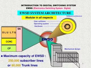
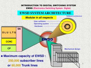
INTRODUCTION TO DIGITAL SWITCHING SYSTEM EWSD (Electronics Switching System Digital). EWSD SYSTEM ARCHITECTURE. Software architecture. Modular in all respects. User software. Operating system. Hardware. D L U / L T G. SN. EWSD. CCNC. CP. Mechanical design.

INTRODUCTION TO DIGITAL SWITCHING SYSTEM EWSD (Electronics Switching System Digital)
E N D
Presentation Transcript
INTRODUCTION TO DIGITAL SWITCHING SYSTEM EWSD (Electronics Switching System Digital) EWSD SYSTEM ARCHITECTURE Software architecture Modular in all respects User software Operating system Hardware D L U / L T G SN EWSD CCNC CP Mechanical design • Maximum capacity of EWSD : • 250,000 subscriber lines or 60,000 Trunk lines
General Information The hardware of an EWSDsystem is organized in subsystems that are linked through uniform interfaces. The Digital Line Unit (DLU) combines a number of analogue and digital subscriber lines. Max 952Subscriber lines can be connected to one DLU. The DLU is connected to the Line/Trunk Group (LTG). The Line / Trunk Group (LTG) not only terminates Digital Line Units (DLUs). It is also linked to: Other exchanges Digital Switching Board (DSB). The Switching System (SN) provides the inter-connections between two subscriber lines. To handles the Signalling System No.7, the EWSD exchange requires a Subsystem Common Channel Signalling Network Controller (CCNC).
EWSD SUBSYSTEMS Access Switching S D C - Digital Line Unit (DLU) - Line Trunk Group (LTG) - Switching Network (SN) - Common Channel Network Control (CCNC) - Coordination Processor (CP) DLU LTG S N 1 DLUC GP S N 0 S D C LTG GP Common ChannelSignaling S D C CCNC CCNP Coordination SYP SYPC S D C E M M B CP MBC G C O M T C C G S G C Distributed controls in an EWSD exchange
Since the processing workload is distributed over several microprocessors within the EWSD system, a common processor for Coordination tasks is extremely useful. These functions are handled by the Coordination Processor (CP). The CP consists of the: Coordination Processor (CP) External Memory (EM) Operation and Maintenance Terminal (OMT) System Panel (SYP) Message Buffer (MB) Central Clock Generator (CCG) Load Distribution In order to reduce the workload of the Coordination Processor (CP) and to achieve faster processing times, some processing functions are distributed over autonomous control devices. Since the EWSD subsystems independently execute all necessary tasks within their respective areas, they require their own control devices,
such as the: DLU •Digital Line Unit Controller (DLUC) LTG •Group Processors (GP) SN •Switch Group Control (SGC) SYP •System Panel Control (SYPC) MB •Message Buffer Control (MBC) CCNC •Common Channel Network Processor (CCNP)
DLU Overview Overview of DLU DLU is responsible for terminating subscriber lines and concentrating subscriber line traffic. The main components of a DLU also include :- - Subscriber line module SLM : SLMA & SLMD - Two DIUD for connection of PDC’s - Two controls DLUC’s - Two 4096kbit/s networks for the transmission of voice and signaling data between the SLMs and the Digital Interface Units (DIUDs). - Two 136 kbit/s control networks for the transmission of control data between the SLMs and the DLU Controls (DLUCs). - A TU for testing telephone, subscriber lines & circuits. D L U Voice and signaling data PDC0 0 SLM A D I U D PDC1 1 . . . Anolog, ISDN & PBX lines D L U C 2 PDC2 SLM D D I U D . . . PDC3 T U D L U C
Line/Trunk Group (LTG) The Line/Trunk Groups (LTGs) are the interfaces between the digital Switching Network and the network environment of the exchange, which may be analogue or digital. For reasons of safety a LTG is always connected to both Switching Network (SN) plane. If the link between the LTG and the Switching Network, or even one plane of the Switching Network fail, call processing will continue without interruption. LTG TYPES: • Line/Trunk Group (LTGA) • Line/Trunk Group (LTGB) • Line/Trunk Group (LTGC) • Line/Trunk Group (LTGD) Functional Types
LINE TRUNK GROUP 2Mbit/s The main components of a LTG are : - Group Processor (GP) - Group Switch or Speech Multiplexer (GS)or (SPMX) - Link Interface Unit (LIU) - Signaling Unit (SU) - Digital Interface Unit (DIU) SU GS OR SPMX LIU DIU0 DLUs PBXs & Trunks 8Mbit/s DIU n GP
Main Functional Units of LTG. • up to 8 line/Trunk Units (LTUs)• signalling Unit (SU) • Speech Multiplexer (SPMX) or Group Switch (GS) • Link Interface Unit between LTG and Switching Network (LIU) The Line/Trunk Units (LTUs) can be connected to: Digital Line Units (DLUs) Other exchanges. Digital Switchboards (DSBs) An LTGB can interface 60 Digital Switchboards (DSBs) via digital access lines. The SU is equipped with code receivers (CR) &Tone Generator (TOG) for generating audible tones
The SPMX is used if the LTG interfaces with trunk lines. The Group Switch (GS) is used if the LTG interfaces with subscriber lines. The GS also handles the 3 party conference calls. SPMX/GS is also multiplexed 4x2 Mbit/sec into 8 Mbit/sec and vice versa. The Link Interface Unit (LIU) is the interface between the LTG and the Switching Network (SN). It : duplicates the channels to both SN planes (SN 0 and SN1). The Group Processor (GP) is an independent periphery controller. GP functions are: controlling all functional units in the LTG exchange data with the Coordination Processor (CP) and other LTGs, self-diagnosis and safeguarding
Line/Trunk Group C & D As the LTGC is used to terminate inter-office trunks while LTGD is used in International Gateway exchange. Switching Network (SN) The actual switching process that establishing a call connection between two subscribers takes place in the hardware subsystem called switching Network (SN). SN Overview For safeguarding reasons, the Switching Network (SN) is always duplicated. The External interface of the Switching Network are the same. They are Secondary Digital Carriers (SDCs) its data rate is 8 Mbit/s. Switching SN consist of Time Stages and Space Stages. A time stage consists of Time Stage Module (TSM) and space stage consist of Space Stage Module (SSM). Each stage consists of its own controller Switch Group Control (SGC)
SWITCHING NETWORK The main components of a SN are : Time Stages In time stages octets to be switched change time slot and highway according to their destination Space Stages In space stages they change highway without changing time slots Switch Group Control (SGC) Connection paths through the time & space stages are switched by the SGC in accordance with the switching information from the CP. T S or SSS T A Sub. B Sub.
Co-ordination Tasks In addition to the Co-ordination Processor (CP) with its External Memory (EM) and the Operation and Maintenance Terminal (OMT), the “Co-ordination” subsystem includes the following functional units: the Message Buffer (MB) with its micro processor control (MBC), the central Clock Generator (CCG) the System Panel (SYP) with its micro processor control (SYPC) CP MAIN FUNCTIONS: The CP performs the following functions Call Processing Operation & Maintenance Safeguarding The Message Buffer (MB) serves as an interface adapter and transmission adapter for the internal information exchange between: CP SN LTGs
CENTRAL CLOCK GENERATOR (CCG) For the transfer of digital information in a network, synchronized functional sequences in all participating units are an absolute requirement. Accurate clock pulses must be provided for all exchanges within the digital network. This task is handled by the Central Clock Generator (CCG). SYSTEM PANEL DISPLAY SYSTEM PANEL ALARMS
– : External alarms Month Day Time Entry Supervision Line/trunk Groups LTG Switching Network SN Fire DC Powersupply Power failure Maintenance Alarm Service Alarm External equipment Aircon-ditioning Coordination Processor CP Message buffer Common Channel Signaling Central Units Clock ERL Processor Load System PanelSYP Trunk Groupalarm Trunk Groupblocked External DLU Alarms HW units Signalinglinks blocked Line Lockout Cat. 1 AdministrativeAlarm Signaling Lines Cat. 2 Recovery Alarm indications suppressed Update Test Accept Call Identification System Operator Time Insecure All external alarm lines of ALEX LED Ex. DLU alarms Each of the 24 external alarm line of RM:EA one LED of Ext. alarms This assignment is stored in EPROM of SYPC (including the alarm priority and the voltage level of the alarm line indication an alarm SYSTEM PANEL DISPLAY
OPERATION AND MAINTENANCE OF THE SYSTEM. Operational Task Subscriber administration Routing administration Traffic administration Tariff and charging administration System administration Maintenance Maintenance of subscriber lines Maintenance of inter-exchange trunks Hardware maintenance Software maintenance