Intro to Digital Electronics
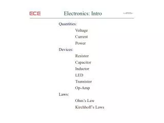
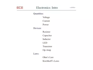
Intro to Digital Electronics. Classifications of Electronic Circuits. Switching Circuits – by turning electricity on and off. Figure 1 Known as the digital method. Regulating Circuits – controls intensity of current. Figure 2 Known as the analog method.

Intro to Digital Electronics
E N D
Presentation Transcript
Classifications of Electronic Circuits • Switching Circuits – by turning electricity on and off. • Figure 1 • Known as the digital method. • Regulating Circuits – controls intensity of current. • Figure 2 • Known as the analog method Figure 1 – Current is On or Off Figure 2 – Increase/Decrease Current
Why Digital? • Digital electronics are simple, practical, and reliable. • Combines simple switches and gates to create electrical functions. • Digital means switching. • HI or 1 (one) or On • LO or 0 (zero) or Off
Truth Table of a Digital Circuit • The operation of the circuit to the right is represented by the table. • Describes switch and output status. • Truth tables represent the operation of a circuit.
Timing Diagrams of a Digital Circuit • Timing diagrams may also represent a digital circuit operation, in this case resistor voltage.
Logic? • Logic circuits are circuits that make decisions based on the inputs they receive. • Remember what the digital signals can be? • 1 or 0; HI or LO; On or Off
Logic Indicators • Logic Indicator is a device that indicates the logic state (either HI or LO) of a certain point in a circuit. • Usually a LED
Boolean Algebra • Conventional Algebra has 4 basic operations • Addition, subtraction, multiplication, division • Boolean Algebra has 6 basic operations • AND, OR, NAND, NOR, NOT, YES • Example: Using the AND Gate • Read as “A anded B equals Q” • Also read as A B = Q • Try using the OR Gate: A Q B A Q B
The AND Logic Gate When is the output of this gate HI? Boolean Equation A B = Q
The OR Logic Gate When is the output of this gate HI? Boolean Equation A + B = Q
The NOT (Inverter) Logic Circuit The NOT logic circuit is also called the “inverter”. Boolean Equation A = Q “A is equal to not Q” Widely used in many circuits; NAND and NOR gates are created by adding inverters to AND and OR gates.
The YES Logic Circuit The input is the same as the output. Also used as: Amplifiers – makes a weak signal strong. Buffers – Isolates delicate circuits Boolean Equation A = Q “A equals Q”
Transistors 3904 3906
The NOR Logic Gate The result of this Gate is always the opposite of an OR Gate. Boolean Equation A + B = Q
The OR Gate vs. the NOR Gate The OR Gate The NOR Gate
The NAND Logic Gate The result of this Gate is always the opposite of an AND Gate. Boolean Equation A B = Q
The AND Gate vs. the NAND Gate The AND Gate The NAND Gate