Delta Angle
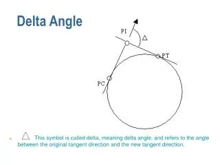
Delta Angle. This symbol is called delta, meaning delta angle, and refers to the angle between the original tangent direction and the new tangent direction. T and L. T is the distance along the tangent from P.C. to P.I. or from P.I. to P.T.

Delta Angle
E N D
Presentation Transcript
Delta Angle • This symbol is called delta, meaning delta angle, and refers to the angle between the original tangent direction and the new tangent direction.
T and L • T is the distance along the tangent from P.C. to P.I. or from P.I. to P.T. • L is the length along the curve from P.C. to P.T. and is computed by formula.
Radius of Curvature • R refers to the radius of curvature. Elements of the Curve Data with which you should be familiar are: T L and R • Study the drawing for the meaning of these symbols..
Curve Data • Given some of the curve data you can compute other dimensions such as: • L = 2πR(∆/360º) where π is 3.14 • T = R tan(∆/2) • PI = PC + T or PRC + T • PT = PC + L • Now that we have determined what the symbols represent, let's find out how to use them. • On any set of plans you will see figures arranged in this manner:S68º 14' 00"E. This is known as a bearing (or direction) and is read as: South sixty-eight degrees, fourteen minutes, naught seconds east. To explain this we will look at a few diagrams.
North, South, East or West • NOTE: Always use the first letter (N or S) as zero, starting point, and the second letter as the direction towards which you turn. • 7. Looking straight down on the top diagram, the arrow is facing due __________________________. • Therefore, if a person is facing South and turns toward the East in the direction of the second arrow, he would be facing South and turn toward the East 68º 14' 00" and would then be facing S68º 14' 00"E. • All bearings in highway work use NORTH or SOUTH as a STARTING POINT and proceed either east or west. The angle cannot be greater than 90º.
Bearings • Check this drawing and note that the bearing of the tangent as it enters the curve (back tangent) is S 68º 14’ 00” E. • On the tangent between the PI and the PT (ahead tangent) a bearing of S 14º 14' 00" E is given.
Bearings • If we plot both of these bearings in the same manner, we find that angle A, formed between SOUTH and bearing S 14º 14' 00" E, is smaller than angle C, formed between SOUTH and bearing S 68º 14' 00" E. • Therefore, bearing S 14º 14' 00 E (Angle A) is closer to SOUTH than bearing S 68º 14' 00 E (Angle C). How much closer (Angle B) is what we have to calculate in order to figure the delta angle. So, subtract 14º 14' 00 from 68º 14' 00". The difference is 54º 00’ 00”, the delta angle.
Bearings • If we re-arrange our diagram by moving bearing S 14º 14' 00 E, tangents are formed and intersect. • We know from geometry that angle B and angle B’ are identical. Therefore, angle B is the same as the delta angle. This is also called the angle of deflection. This is the angle that you would have to turn in order to leave a bearing of 68º 14' 00” E and begin a bearing of S 14º 14' 00” E. • 8. In this case, the delta angle, or angle of _______________is_________ degrees.
= Equality • In the center of this drawing you will note a vertical line topped by a black and white checkered circle. This is called an EQUALITY. This is like a flag! • This particular point along the baseline has TWO station numbers. The one that is used depends on the direction in which you're going. Here the 417+22.60B’k relates to the stations back of this point and 417+41.79Ah’d relates to the stations ahead of this point. When working with distances across this point you should add the distance to this point from back and to this point from ahead. Do not just subtract stations on different sides of Equalities. • There are numerous reasons for establishing an EQUALITY and they will be covered later. Right now all we're concerned with is how to compute measurements across equalities.
Equality • As an example: To determine the distance along the baseline from sta. 415+00 to sta. 420+00, start at one end and measure up to the equality using the value on the same side of the line as your starting point: • from sta. 415+00 to sta. 417+22.60 = 222.60 ft. • Now start with the value on the other side of the line and measure to your destination: from Sta. 417+41.79 to sta. 420+00 = 258.21 ft for a total of 480.81 ft • So the total distance from station 415+00 to sta. 420+00 is not 500 ft as you might expect at first glance. In other words, you have a negative equality, and the length of that equality is minus 19.19 feet. Between 415+00 and 420+00 is 500 – 19.19 = 480.81 ft.
Equality • Take another look at the equality. Notice that one side of the equality says POT 417+22.60 B'K (BACK) and the other, 417+41.79 A'HD (AHEAD). Always subtract your AHEAD station from your BACK station. This is true even if your AHEAD station is larger. For example: • For this example the results are negative (a negative equality): 417+22.60 B'K subtract 417+41.79 AH'D -19.19 feet • If your AHEAD station is smaller than your BACK station, simply subtract and you will arrive at a plus figure. You now have a PLUS EQUALITY, and an important thing to remember in cases like this is that you will have more than one station with identical numbers. That is why we use the words BACK (BK) and AHEAD (AHD).
Let’s see how it works • Notice that there are 2 stations 158+19.18 and 2 stations 159+19.18. That is why we have a sta. 159+19.18 B'K and sta. 158+19.18 AH’D. • Using the procedure we learned earlier, measure the distance from sta. 157+00 to sta. 160+00. The distance from station 157+00 to 159+19.18 B’K (back) is 219.18 feet. The distance from station 158+19.18 AH’D (ahead) to 160+00 to is 180.82 feet. Adding 219.18 and 180.82 produces a total of 400 feet. This is the actual distance from station 157+00 to 160+00, not 300 feet as you may expect. This is due to the equality which is because an even 100 feet was added to the baseline length. Often the baseline length is not increased or decreased an even number of feet, however the principle is the same as described here. Pay particular attention when measuring distances involving plus equalities.
9. Determine the distance from station 157+50 to station 158+19.18 B’K in feet. _______________________________. • 10. Determine the distance from station 159+19.18 B’K to station 158+19.18 AH’D in feet. _________________________.
Equality • We mentioned earlier that there are many reasons for using EQUALITIES. Perhaps the following illustration will help explain one of them: • After the baselines are laid out by the survey party, portions of the alignment sometimes have to be changed. This requires an increasing or a decreasing of distances between certain stations. Where the new line converges with the old line, the station numbers will not agree. This is due to the differences in the distances of the old and new line. • To re-survey the entire route to conform to the new length would be a tremendous task, and would require revision of many records, so equalities are created. This requires no changes in the stationing of the undisturbed portions of the highway.
Equality • For example: Let's take an alignment where the PC is sta. 12+02.00 and which runs 1271.00 feet to the PT at sta. 24+73.00. It is decided to straighten the highway by projecting a tangent between these two points. • The length of this new tangent is 850.00 feet. Therefore, the station at the point of tie-in of the new line and the old line will become 20+52.00. • This point then is designated as Sta. 24+73.00 AH’D and Sta. 20+52.00 B’K. Notice that by retaining the old station 24+73.00, we can continue along the baseline without changing station numbers beyond the point of tie-in. • What we have actually done is taken 421.00 feet out of the baseline.
Equality The old line was 1271.00 feet The new line is 850.00 feet The difference is 421.00 feet
Equality • The PC is sta. 12+02.00. Drop the (+) and we get a distance of 1202.00 feet. By adding the length of the old line, which is 1271.00 feet, you end up with 2473.00. Divide by 100, slip your (+) back in and you get sta. 24+73.00. • Now, by subtracting the AH’D STATION from the B’K, STATION as previously covered, you'll find the length of the equality is minus 421.00 feet.
Proposed Easement • So far we have examined only the baseline. Let's check out a few other features found on a Plan Sheet. On some plans you will note the words "proposed easement" with the following symbol: 50’ 80’ + 50 80’ • This easement break point describes a point 80 feet off the base line. • The 80 feet is measured perpendicular to the base line at the nearest station plus 50 feet. • These break points are read the same as Right of Way break points.
Plan Sheet • In the upper left hand corner of each Plan Sheet you will find information as to the ownership of power and telephone poles which may have to be moved during the course of construction. • On the Title Sheet are found the appropriate symbols for power and telephone poles. • The Plan Sheets graphically illustrate other features such as Construction Limits, Right of Way lines, R/W Break Points, Property Lines, Property Owners, and Parcel Numbers.
Plan Sheet • The scale drawn in the lower right hand corner of the plan sheet is called a Horizontal Scale and indicates the ratio of the horizontal distances on the plan sheet compared to the actual horizontal dimensions on the ground. • Normally full size Imperial plans are at a scale of 1 inch equaling 100 feet. • There are times when you will be using reduced size (usually half-size) plans in the field. It is important to realize that the scale will also be half-size. • On the Title Sheet, the scale is much smaller, such as 1 inch equals 2000 feet. The smaller scale is necessary to depict the entire project on one sheet.
Profiles • So far we have been concerned mainly with the PLAN view. • From a Plan view, it can be determined whether the road is curving to the right or to the left, or going straight. This is referred to as the horizontal alignment. • Just as roads curve left and right in their horizontal alignment, they sometimes curve up and down. This is known as the vertical alignment. Curves along the vertical alignment are called vertical curves.
Vertical Curves • To study vertical curves we must look at the PROFILE. • Remember that we said that we had to look at the highway from one side or the other in order to get a PROFILE (side) view.
Profiles • The horizontal scale is the same for both the Plan and the Profile sheets. • In addition, the Profile Sheet has a numerically graduated vertical scale along the left and right margins to measure elevation. • This scale is usually 1 inch equals 10 feet; however, this is not always so. • A look at the Profile Sheet will tell you just what the scale is for that particular profile.
Profiles • Study this drawing and determine the horizontal and vertical dimensions of block "A". • If you came up with a 50 ft horizontal distance and a 10 ft vertical distance you're correct. Notice that the height exceeds the width considerably. This exaggeration is necessary in order to amplify the grade to a point where it is discernible. This provides an easier view of the profile.
Profiles • Notice the exaggeration of vertical scale versus horizontal scale in the above 50’ by 50’ area in blue. • Because of the ratio of vertical (up and down) changes compared to the horizontal distance along the road, which makes it hard to see, it is necessary to enlarge the vertical scale so the up and down changes can be more easily seen.
Profile Drawing VSD=239ft V=35mph • The heavy line represents the baseline (planned elevation) of the road upon completion of the project. The thin dashed line below or above the baseline (proposed grade) represents the existing grade. Where this line is above the proposed grade, a CUT is necessary; where this line is below the proposed grade, a FILL is required. When both the existing and proposed elevations are the same it is known as a GRADE POINT.
Profile vertical scale VSD=239ft V=35mph • In the right and left hand margins of this Profile Sheet locate the numbers 859, 858, 857 and 856. This is the vertical scale and it indicates the elevation of the existing and proposed grade as determined by some reference point, usually sea level.
Profile station numbers VSD=239ft V=35mph • Below the profile are figures across the sheet indicating station numbers such as 119+00 and 121+00. Every station on the profile corresponds to that same station on the plan sheets. Just above each of these numbers are vertically written numbers; these are the elevations of the new road at the respective stations.
Profile finished grade VSD=239ft V=35mph • Across the sheet are stations and elevations for the profile, such as 120+00, elev. 857.96. This means that the POINT OF FINISHED GRADE at the baseline is 857.96 feet above some reference point. This elevation refers only to the baseline. Follow the line straight up from 120+00 to intersect the heavy line on the profile and follow a line directly over to the right vertical scale to see the 857.96 ft elevation.
Profilegrades VSD=239ft V=35mph • On the profile you will see the figures –2.28% and +1.52%. These refer to THE PERCENT OF GRADE. Grades that are going downhill are designated negative (-) grades. Grades going uphill are designated positive (+) grades. • The figure –2.28% indicates that the grade falls 2.28 ft vertically for each 100 ft of horizontal plane. This method of calculation is true for all straight grades whether uphill or downhill.
Profilevertical curve VSD=239ft V=35mph • From station 119+33 (PVC) (point of vertical curve) to 120+63 (PVT) (point of vertical tangent) is a vertical curve. The tangents to and from this curve intersect at station 119+98 (PVI) (point of vertical intersection). Elevations at 25 ft intervals are listed for the curve at the bottom of the profile. Check your vertical scale and you will find that at Sta. 119+98, the PI is at an elevation of 858.59 ft; at Sta. 121+00 the tangent elevation is 856.26 ft; a drop of 2.33 feet. This is a drop of 2.33 ft in 102 feet which is 2.28%.
Profile elevations VSD=239ft V=35mph • The elevation of the baseline profile is determined by multiplying the PERCENT OF GRADE by the distance in feet from the last known elevation (written along the bottom of the profile) and subtracting or adding the result obtained from the previous elevation. • To compute the elevation at station 120+80: The elevation is 856.83 feet at Sta. 120+75. From Sta. 120+75 to Sta. 120+80 is 5 feet. The grade is – 2.28%.
Profile elevations VSD=239ft V=35mph • Converting – 2.28% to decimals produces – .0228. Remember that for every 100 feet of distance, you'll drop (minus) 2.28 feet. Multiply 5 feet by .0228 and you'll get 0.11 feet. Subtract this figure from the last known elevation of 856.83 ft at Sta. 20+75, and you have the elevation at Sta. 120+80 of 856.72 feet.
Profiles - computing elevations • There are several items to remember in order to prevent making an error in computing elevations. • When calculating the distance, do not overlook an EQUALITY. This could create quite an error. • Make sure that with minus (-) grades (going down), you subtract the vertical drop when on the downhill side of the previously known elevation. • Likewise, remember that plus (+) grades are going up and therefore you must add the vertical rise when on the uphill side of the known elevation.
Parabolic Vertical Curve • To determine offsets from the tangent to the parabolic vertical curves there are several terms and equations: • C.G. = Point of change of gradient. • C = Center correction. • C’ = Correction at any given point on curve. • D = L/2 = Half length of vertical curve. • D’ = Distance to point where correction is required from beginning or end of curve. • C = Algebraic Difference X length of curve in stations / 8 • C’ = C (D’/D)2