Download
1 / 45
450 likes | 850 Vues
Masters Project Presentation Low Level Design of an Autonomous Vehicle. Presented by Hemanth Tippareddygari Dept of Electrical and Computer Engineering Bradley University. Acknowledgements. Dr. Donald R. Schertz Professor of ECE. Dr. Brian D. Huggins

E N D
Masters Project PresentationLow Level Design of an Autonomous Vehicle Presented by Hemanth Tippareddygari Dept of Electrical and Computer Engineering Bradley University
Acknowledgements Dr. Donald R. Schertz Professor of ECE Dr. Brian D. Huggins Department Chair and Official Gofer of ECE Mr. Steve Gutschlag InstructorofECE Mr. Nick Schmidt, Assistant Lab Director Friends and others.
Contents • Introduction • Microcontroller • Code warrior IDE • Processor Expert • Embedded Beans • Motors • Linear Actuator • Gear tooth Sensors • Ultrasonic Sensors • Serial Communication • Results • Future Work
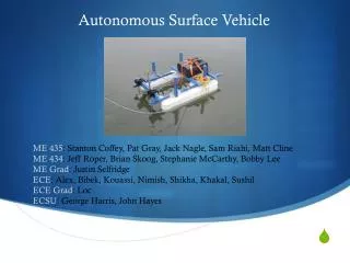
Introduction Gaucho is a self powered sidewalk machine modified to permit electronic actuation of the steering.
Micro-controller • The Micro-controller that I have used is 16-bit Motorola 68HC9S12DG256BCPV on EMAC’s IPAC Board • The main objective of the project is to control the Autonomous vehicle using Motorola 68HCS12 Microcontroller
Micro-controller • Features: • MC9S12DG256BPCV microcontroller - iPac HC(S)12 from emac inc. - 16-bit CPU-based micro-controller 16-bit data bus and 16-bit address bus - Queue instruction mechanism executes up to one instruction per clock cycle - Operates up to 25MHz clock speed - Memory 256K Flash EEPROM, 4K EEPROM, 12K RAM - On chip peripherals ECT, PWM, SCI, IIC, CAN, SPI, A/D
Micro-controller - BDM Interface P&E’s USB HCS12 MULTILINK Interface provides access to the Background Debug Mode on Free scale HCS12 microcontrollers. It is the hardware interface between a USB port on a Windows 2000 or XP machine and the standard 6 pin “Berg” debug connector on the target.
BDM Interface The user can directly control the target’s execution, read/write registers and memory values, debug code on the processor, and program internal or external FLASH memory devices with the advantage of BDM interface. BDM module can operate asynchronously with the rest of the HCS12 system and access the on-board memory without stopping processor unlike micro-controllers with JTAG debugging. PIN OUT
Code warrior IDE • Code warrior IDE is a complete Integrated Development Environment which provides various tools like Real time debugger, Full chip simulator, Processor expert beans, Compiler, Linker, Assembler, Project Manager, Search Engine, Text Editor etc
Processor Expert • Processor Expert is designed for rapid application development of embedded applications for a wide range of microcontrollers and microprocessor systems • Processor Expert works with an extensible beans library of supported microprocessors, peripherals, virtual devices • Code generation from beans by Processor expert creates the ability to maintain user and generated code, and an event based structure significantly reduce the programming effort
Embedded Beans • Embedded Beans encapsulate functionality of basic elements of embedded systems and change these facilities to properties, methods and events • Embedded Beans are programming language independent, they can hold any language including assemblerprovides more reuseability and an easy system configuration • If Embedded Beans are configured as per the requirements the Processor Expert generates the code and the desired output is obtained at any of the ports
Embedded Beans • Internal Peripherals - PWM - ECT - SCI - ADC - BitIO • External Devices - SPI - I2C
Motors • 2 DC Motors in the back wheels of Gaucho • High Power H–Bridge DC Motor Driver Board • PWM signal to control the speed of vehicle • Direction input to control the direction of the vehicle
D-200 Model 2 H-Bridge Driver Boards for each motors. 5 Volts for the Digital and MOSFET Bias Circuitsand any voltage up to 55 volts for Motor B+. 10 A rated current without heat sinks and 60 A max current with proper heat sinks.
D200 Connections Control lines
The Truth table for the control signals to this H-Bridge is shown below. Motor - Control Lines
Motor - Control Lines • To control the speed of the motors with PWM, the PWM signal from the processor is applied to Enable Input line. • The PWM signal applied to this motors have a frequency of 1 KHz or less. • Direction signal from Processor is applied to both the IN1 and IN2 input lines.
“PWM” Bean • This bean implements a pulse-width modulation generator that generates signal with variable duty cycle and fixed period. • The fixed period of 10ms is selected and variable pulse width for different duty cycle is also selected. • Output pin in Port P is selected to get the desired PWM signal at that pin.
PWM – O/P Waveforms 25% Duty cycle 50% Duty cycle 75% Duty cycle
“BitIO” Bean • This bean "BitIO" implements an 1-bit input/output. It uses one bit/pin of a port. • This bean has a subroutine called Putval(value). If direction is input saves the value to a memory or a register, this value will be written to the pin after switching to the output mode. • If direction is output writes the value to the pin.
Linear Actuator • Linear Actuator with potentiometer • Steering Control • LMD 18200 H- Bridge Driver Circuit • PWM Input from Processor • Direction Input from Processor
LMD 18200 • This chip is a H-Bridge designed for motion control applications • It delivers up to 3A continuous output • Operates up to 55v of supply voltage • Generally used as DC & stepper motor drives. • Control lines for this H-Bridge are PWM Input, Direction Input and Brake Input from the processor.
LMD 18200 Driver Test Circuit
Gear Tooth Sensors • Hall Effect Sensors are mounted on inner part of the wheel. • This sensors are used to calculate the distance traveled by the vehicle. • Speed of the vehicle is also determined by this sensors. • Output from this sensors is a pulse whenever it passes through a screw.
Gear Tooth Sensors • Although commonly called a gear tooth sensor, it is a solid-state speed sensor that can detect the motion of various ferrous objects with some type of discontinuous surface. Block Diagram
Ultrasonic Sensors • SRF04 Ultra-Sonic Ranger • The SRF04 was designed to use easily as the Polaroid sonar, requiring a short trigger pulse and providing an echo pulse. • The length of this pulse is determined by the controller to find the range of the object. • A supply of short 10 microsecs pulse to the trigger input is needed to start the ranging.
Ultrasonic Sensors • The timing diagram for SRF04 is shown below
Timer Capture Bean • The distance of the object is determined by calculating the pulse width of the echo pulse. • To calculate the pulse width timer module is used in the processor. • The timer bean has an extensive feature of input capture in it. • This bean implements the capture function of the timer.
Timer Capture Bean • On the selected edge of the input signal, the current content of the counter register is written into the capture register and the OnCapture event is called. • Capturing the values of 2 consecutive Falling or Rising edges of the PWM and subtracting the higher value from the lower value gives the period of the PWM signal. • Capturing the values of one rising and next falling edge of the PWM and subtracting them gives the Pulse width of the signal.
Ultrasonic Sensors • SRF04 provides an echo pulse proportional to distance. • The pulse width from capture bean measured in number of ticks is converted in to uS. • If the width of the pulse is measured in uS, then uS/58 gives distance in cms, and uS/148 gives distance in inches. • This Distance tells the distance of an object in front of the vehicle.
Serial Communication • The need to exchange data between the MCU and peripheral devices can be satisfied by using parallel data transfer. • The Serial Communication Interface (SCI) was designed to transfer data in asynchronous mode that utilizes the industrial standard EIA-232 protocol. • The EIA-232 was originally called RS-232.
RS-232 • RS-232 standard was established in 1960 by EIA for interfacing between the computer and a modem • Computers and terminals are called DTE • Modems, bridges and routers are called DCE • RS-232 is applicable to data rated up to 20,000 bits per second
RS-232 • The TD (transmit data) wire is the one through which data from a DTE device is transmitted to a DCE device. • The RD (receive data) wire is the one on which data is received by a DTE device, and the DCE device keeps this line in a mark condition when idle.
RS-232 • The expected waveform from the UART when using the common 8 Data bits, No Parity and 1 Stop Bit format. • The RS-232 line, when idle is in the Mark State (Logic 1). A transmission starts with a start bit which is (Logic 0). Then each bit is sent down the line, one at a time. • The LSB (Least Significant Bit) is sent first. A Stop Bit (Logic 1) is then appended to the signal to make up the transmission.
“AsynchroSerial” Bean • This bean "AsynchroSerial" implements an asynchronous serial communication. The bean supports different settings of parity, word width, stop-bit and communication speed, user can select interrupt or polling handler • Communication speed can be changed also in runtime. • The bean requires one on-chip asynchronous serial channel. • The baud rate selected to transfer data is 19200 bits per second.
SCI • Communication is done using HyperTerminal • This terminal program is an application that will enable a PC to communicate directly with a modem. • The COM port and its settings like the baud rate, data bits, parity bit, stop bits are set.
Commands • Commands used for controlling the vehicle are F – Forward direction B – Backward direction R – Turn Right L – Turn Left s – To Stop One more character follows F and B to tell the speed of the vehicle. Two more characters follows R and L to turn the car to a particular angle. To stop the car immediately “s” is used.
Results • Hardware interfacing between all the modules and the processor. • Wrote the code with the help of processor expert. • Controlled the vehicle by passing messages serially to the processor from the Laptop.
Future work • To calculate the distance and speed traveled by the vehicle with gear tooth sensors. • More sensors are used to determine the surroundings of the vehicle. • Before starting the vehicle, the angle of the steering can be given to the user using SCI.