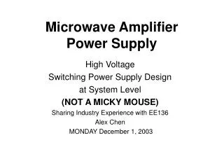
Microwave Amplifier Power Supply
Microwave Amplifier Power Supply. High Voltage Switching Power Supply Design at System Level Sharing Industry Experience with EE136 Alex Chen MONDAY December 1, 2003. BASICS of Traveling Wave Tube (TWT) Amplifier. Reference: http://www.twtas.com/pictures/factorywalk/faccathode.html.


Microwave Amplifier Power Supply
E N D
Presentation Transcript
Microwave Amplifier Power Supply High Voltage Switching Power Supply Design at System Level Sharing Industry Experience with EE136 Alex Chen MONDAY December 1, 2003
BASICS of Traveling Wave Tube (TWT) Amplifier Reference: http://www.twtas.com/pictures/factorywalk/faccathode.html
Key Notes of TWTA: • Heater/Filament is closest to Cathode Voltage. • Heater and Cathode act as electron gun, and they are on the side RF Input. • Collectors sits on RF output. • Electrons are fired from Cathode and received from Collectors. • RF signal is amplified through bunching effect after traveling along the path of Helix coil.* • Higher Cathode voltage Higher RF Power * • Advantage of TWTA (over solid state amplification) is the linearity and output power* • TWTA Efficiency: 50% to 60% vs. Solid State: 25% to 30% • Ranges of Frequency for TWTA: 1Ghz – 40 Ghz • *Additional Information: • http://www.djmelectronics.com/articles/twt-vs-solid-state.html
Application of TWTA • Point to Point Communication • Satellite communication and Rader Appz • Missile tracking application for military • Television live broadcasting • LIVE news vans with satellite dishes on the roof carry TWTA inside
Specification of Communication TWT: MODEL NO. MEC 5417D FromTELEDYNE Electronics
Key Notes for Reading the Specification of TWTA: • Cathode (Ek) Voltage is NEGATIVE. • Collector 1/2 reference to Cathode Voltage • Collector Voltages read POSITIVE • Heater Voltage also references Ek • Test Equipments (Ex: 1kX Divider) are reference to Ground GROUND Collector 1 Collector 2 Cathode Heater Comparing Relative Voltages -10kV +6kV +4kV -6V
Left: 600W Tri-band CW TWTARight: Power Supply Products of ETM Electromatic Inc.www.etm-inc.com Interchangeable module-type Power Supply
More Products • Astrium Project for Skynet: -15kV Cathode Voltage Power Supply (Far Left)-RF Amplifier by CPI (Right) with input RF source (front)Output dummy load (back) 4-Astrium Units Combined for Project Skynet
High Voltage Filters Ready to be Tested Right: High-Voltage Filters after assembly ready to be testedLeft: Potted filters to be retested (*Potting materials = High-Voltage Insulation)
Testing High-Voltage High-Voltage modules are tested in flouriner (liquid insulator) before potted with liquid silicone rubber
Block Diagram of Switching PS ~ + ~ - HV Filter ~ - ~ + ~ - ~ + ~ - ~ + DIODE
Major Components • Input Filter or PFC • H-Bridge: Buck + Full-Bridge • Pulse Width Modulation for H-Bridge • Diode • High-Voltage Filter • Heater • Grid Modulator • AC Fan Driver for cooling • Logic & Control • Human Interface Control • Low Voltage Power Supply RED: Topics will not be discussed in class
Presentation Notes: • Input Filter • LRC filtering with delay and soft-start • Phase Loss detection circuit • H-Bridge • Isolated Buck Converter to Full-Bridge • PWM controls Buck Converter. • Duty of Full-Bridge is fixed at 50%. • The use of transformers for gate driver circuits • PWM Board • Controls both buck drive and full-bridge. • Master/Slave Configuration for Buck to Full-Bridge • Gate Driver Chips • Pre/Post Regulation • Diode • Primary and Secondary Transformers • Voltage Doublers Circuit • High-Voltage diodes are used for rectification • High-Voltage Filter • RC Low Pass Filter • Feedback sense from Cathode Voltage to PWM • Post Regulation • Arc Detection
Presentation Notes (continue): • Fast Heater • Forward Regulator • Same chip as PWM chip • Two different voltage reference • Single-shot re-triggerable chip • Voltage Sense / Current Sense • 400Hz Sinus Fan Driver • Boost, Half Bridge, Flyback • Hi/Low sides driver • Microcontroller with oscillator • Over voltage / Over Current Detection