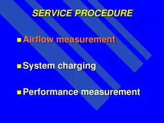
SERVICE PROCEDURE
SERVICE PROCEDURE. Airflow measurement System charging Performance measurement. Airflow measurement. An accurate airflow measurement must be performed before the system can be properly charged with refrigerant or before any attempt is made to measure performance. Airflow measurement.

SERVICE PROCEDURE
E N D
Presentation Transcript
SERVICE PROCEDURE • Airflow measurement • System charging • Performance measurement
Airflow measurement An accurate airflow measurement must be performed before the system can be properly charged with refrigerant or before any attempt is made to measure performance.
Airflow measurement BTUH (OUTPUT) CFM = TEMP DIFFERENCE X 1.08
Measurement Methods • power measurement - watt-hour meter • electric resistance heat and heat pumps • power measurement - volt-ampere • electric resistance heat • clocking a gas meter • natural gas furnaces • calculating input by orifice capicity • propane gas furnaces • total static pressure
WATT-HOUR METER • Power input measurements, by the watt-hour meter require power interruption to all appliances in the structure except the indoor fan motor and electric heaters. • Do not turn off power to: • Life support devises • Appliances subject to damage from power interruption
WATT-HOUR METER • Set the thermostat to heat or emergency heat and adjust the setpoint to 90 degrees. • Locate the watt-hour meter serving the structure. • Clock the black mark on the meter disc for 20 revolutions using a stop watch or the second hand on your wrist watch.
Power Input Formula Revolutions x KH factor x 3.6 KW (KILOWATT) INPUT = Seconds 20 revolutions kh = 7.2 65 seconds
Power Input Formula 20 rev x 7.2 kh x 3.6 518.4 KW = = = 7.97 kw 65 65
1 KW = 3413 BTU PER HOUR 7.97 kw x 3413 = 27,202 btuh (input) electric resistance heat is 100% effecient input = output
Take Return Air Temperature Measurement as Close to Equipment as Possible
Do NOT Take Temperature Measurement in the Line of Sight of Heat Source.
Airflow measurement BTUH (OUTPUT) CFM = TEMP DIFFERENCE X 1.08 EXAMPLE: 27,202 BTUH (output) 27 degrees delta “T”
Airflow measurement 27,202 BTUH 27,202 BTUH CFM = = = 933 CFM 27 X 1.08 29.16
Measurement Methods • power measurement - volt-ampere • electric resistance heat
POWER MEASUREMENT VOLT-AMPERE • set the thermostat to the heat or emergency heat mode, in the case of a heat pump, so that only the resistance heaters and the fan motor are activiated. • measure the applied voltage to the resistance heaters while they are operating. • measure the current draw for each circuit if more than one and add them together. • measure the temperature difference entering and leaving the air handler.
POWER MEASUREMENT VOLT-AMPERE • multiply the applied volts times the total current draw (amperes) VOLTS X AMPERES = WATTS BTUH (OUTPUT) = WATTS X 3.413
Measurement Methods • Clocking a gas meter • Natural gas furnaces
2 cubic feet per revolution
GAS FURNACE INPUT • make sure no other appliances are on during the test. • set the thermostat to heat mode and 90 degrees. • record the seconds required for one revolution of the 2 cubic foot dial on the gas meter. • determine the gas flow rate in cubic feet per hour from the following equation or use a gas flow table.
GAS FURNACE INPUT 2 cu. feet per revolution x 3600 cu. ft per hour =
GAS FURNACE INPUT 2 cu. feet per revolution x 3600 cu. ft per hour = time (in seconds) per revolution
GAS FURNACE INPUT 2 cu. feet per revolution x 3600 cu. ft per hour = time (in seconds) per revolution example: 1 rev. (2cu.ft. dial) = 60 seconds
GAS FURNACE INPUT 2 cu. ft. per revolution x 3600 cu. feet per hour = 60 2 x 3600 7200 cu. feet per hour = = = 120 CFH 60 60
60 SECONDS 120 CFH
GAS FURNACE INPUT BTUH = HEAT CONTENT X CUBIC FOOT/HOUR BTUH = 1000 BTU X 120 CFH = 120,000 BTUH (INPUT) BTUH (OUTPUT) = BTUH (INPUT) X EFFECIENCY USE A MIN. OF 80% EFFICIENCY FOR NAT. GAS USE FURNACE AFUE EFFECIENCY IF HIGHER THAN 80%
GAS FURNACE INPUT 120,000 BTUH X 92% CFM = 55 X 1.08 110,400 BTUH (OUTPUT) CFM = = 1858 CFM 59.4
Measurement Methods calculating input by orifice capacity • propane gas furnaces
CALCULATING CFM AND INPUT BY ORIFICE CAPACITY • determine the burners orifice size. • count the number of orifices in the furnace. • set the gas valves outlet manifold pressure to 11 inches of water column. • set the thermostat to heat mode and 90 degrees. • measure the temperature difference entering and leaving the furnace.
CALCULATING CFM AND INPUT BY ORIFICE CAPACITY • determine the btu per hour input for the selected orifice size using table f-2 in apendix f of the national fuel gas code. • multiply the btu per hour input times the number of orifices counted in the furnace. • multiply the btu per hour input times the furnace effeciency (minimum 80%).
Measurement Methods • total external static pressure
STATIC PRESSURE Definition: The pressure measured above or below atmospheric pressure created by the blower independant of air velocity. It is exerted in all direction to the inside walls of the ductwork and is measured at a 90 degree angle to the airflow.
Measure return static pressure close to air handler or furnace cabinet. messure return static pressure as close to air handler or furnace cabinet as possible
Measure supply static pressure downstream of all pressure drops. Average readings where turbulant airrflow is present
PRODUCT DATATWEO48C140B - BAY96X1415PUB # 22-1298-03 PAGE # 8 • EXAMPLE: Measured external static pressure = .5 In. W.C. Blower set on high speed tap
Product DataTWE048C140B - BAY96X1415 • EXAMPLE: Measured external static pressure = .5 In. W.C. Pressure drop accross heater = .13 In. W.C. Final static pressure = .63 Airflow = approx. 1550 CFM
TUD100C948H - TXC049C4HPB • EXAMPLE: Measured external static pressure = .30 In. W.C. Blower set on black - high speed tap
Product Data TUD100C948H - TXC049C4HPB • EXAMPLE: Measured external static pressure = .30 In. W.C. Pressure drop accross coil = .30 In. W.C. Final total external static pressure = .60 In. W.C. Blower set on black - high speed tap Airflow = 1595 CFM
Product Data TUD100C948H • EXAMPLE: Temperature rise = 47 degrees Airflow = 1550 CFM