Download
1 / 17
170 likes | 712 Vues
G. LAST. urst. B. onitor. M. Calibration Overview – August 31, 2004 J. Fishman. Calibration Plan of the GBM . GBM-MPE-PL-1-1, issue date: Dec 2003 >> GBM-PLAN-1016, Baselined at CDR By Jerry Fishman and Giselher Lichti Purpose

E N D
G LAST urst B onitor M Calibration Overview – August 31, 2004J. Fishman
Calibration Plan of the GBM • GBM-MPE-PL-1-1, issue date: Dec 2003 >> GBM-PLAN-1016, Baselined at CDR • By Jerry Fishman and Giselher Lichti • Purpose • Outlines the plans for the calibration of the NaI and BGO detectors • Flight Det. Calib. Performed at three places: MPE, NSSTC and Spectrum Astro • Ancillary, Off-line Measurements at Low and High Energies • Generation of detector response matrices (DRMs) for NaIs and BGOs • Verification of detector-module requirements Part I : Comprehensive Detector Calibrations at MPE : >TP100 (NaI) , TP110 (BGO) & TP 120 (Mag. Suscept.) Part II:Low Energy X-ray Calibrations with NaI Flight Spare Detector at the PUMA or BESSY X-ray Facility at MPE - TP 101 (NaI) Part III,IV: Long/Short calibration (TP630/635) (– these are really verifications) Part V: Aliveness test (TP105/115) Part VI: Spacecraft Radioactive Source Survey (TP805) Part VII: High-Energy Tests with the BGO Flight Spare Detector (TP111)
Detector-level Calibrations • 1. Channel-Energy Relation & Energy Resolution at Different Energies (on-axis; covering the whole energy range) • 2. - Angular Response – relative values of Efficiency vs. Energy (Used to compare to Monte Carlo Detector Response Matrices, DRMs) • 3. - Angular Dependence of Energy-Channel Relationship and Energy Resolution (Performed at same time as #2, above) • 4. - Rate-Dependence of #1 - over several rates, up to 105 cps • 5. - Temperature Dependence of #1, in operating temperature range
Detector Magnetic Susceptibility • GBM-PROC-TP120: • In three orthogonal axes, +/- 1.5 gauss • Uses radioactive source to measure gain (Na-22) • Detailed Procedure outlined in GBM-MPE-PL-11, A. von Kienlin, July 2004 • Helmholtz coils in MFSA Ottobrunn facility, Germany • 26 orientations planned
Other Calibrations and Related Activities • Some Calibrations will be verified in Huntsville, after detector delivery and also at the S/C Facility after integration on the spacecraft (These are termed Long and Short Calibrations) • Scattering Measurements will be made at Spectrum Astro Post-integration to assess spacecraft scattering radiation into the detectors, see PLAN-1016. Source strengths ~5-10 mC . (Preliminary requirements have been given to Spectrum Astro) • The Low Energy Calibrations (~5-35 keV) have several options and are currently under discussion within the GBM team. • Some Limited Calibrations at a High-Energy Particle Accelerator (Perhaps a science model only) – Duke University is the baselined facility • It would be highly desirable to have a quick data run at Spectrum Astro using a portable van de Graff generator (ref. E. Bloom)
NaI/BB - Spectra NaI Energy Calibration - Note linearity and low energy response
Low Energy Calibration Sources IsotopeEnergy Am-241 17, 60 keV Cd 109 22, 88 keV Ba-133 32, 81 keV Bi-207 8, 12, 75 keV Co-57 14 keV
Low Energy Calibration – Additional Tests MPE is planning to perform a separate Low Energy Calibration on one or two non-flight NaI detectors (TP 101) at either PUMA facility at MPE or the BESSY facility in Berlin These tests will be done mainly to explore subtle non-linearities at low energies and across the Iodine k-edge
g - source g - source g - source NaIDetector g - source BGODetector Rate Dependence • Measurement of rate dependence of • Channel-Energy Relation • Energy-Resolution • as a function of counting rate • 2 NaI – detectors: (TP100-D) • 109Cd, increasing count rate in steps up to 100 kcps • 22Na, increasing count rate in steps up to 20 kcps • 1 BGO: (TP110 -D) • 137Cs and 24Na • Increasing count rate in steps up to 20 kcps
Low Energy Tests - The PUMA X-ray Test Facility • Vacuum system • Length: 6 m • Main instrument chamber • Length: 2 m • Diameter: 1.6 m • 10-7 mbar • Front door opens into class 10 clean room • Multi-target X-ray source • produce a bunch of X-rays in the energy range 0.5 – 17 keV • energy spread: natural line width • Beam flux: 104 photons/(cm² s) • Collimators system inside vacuum tube • Monitor counters • silicon drift chamber detectors • absolutely calibrated • Accuracy for spectral flux density 2 % • GBM test with Puma (TP 101): • FM NaI detectors (number: TBD) • With flight-like thermal cover • Energy range: 3 – 17 keV • At different incidence angles
BGO - High energy tests • The Duke University Free-Electron Laser Facility (DFELF) will be used for the GBM High Energy Gamma-Ray Calibration • at the high intensity gamma source location • utilized for tests of the MPE Mega Project • calibrations will be performed at least six months prior to launch on the flight spare BGO detector • test for non-linearity and saturation effects in the BGO crystal and PMT • energy range: 2 - 35 MeV
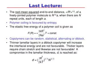
The High Energy Gamma-ray Source at the Free-Electron Laser Lab. (FELL) Duke University, Durham, NC Beam Calibration of the MEGA Prototype (Medium EnergyGamma-Ray Astronomy, 0.4 – 50 MeV)
Storage Ring, Free Electron laserInverse Compton Beam RF cavity injection e--bunch 1 e--bunch 2 laser pulse 1 mirror mirror -ray beam wiggler
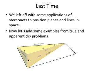
-ray vault linac storage ring collimator hut wiggler mirror The High Intensity -ray Source (HIS) free electron laser
Verifications, not really Calibrations, in Plan #1016 • Long Calibration (TP 635) • Purpose: Check gain and resolution of all detectors • before and after major tests, such as vibration, thermal-vacuum • before and after shipping of the detectors • will be performed at MPE, NSSTC and Spectrum Astro • Short Calibration (TP 630) • TP 635 with a sub-set of selected detectors • Can be performed at various phases of the integration • Aliveness Test (NaI: TP105, BGO: TP115) • natural background radiation will be used to ascertain that all detectors are functioning
Calibration Summary Test Procedure Development Cal. Element & TP Nos. Detectors/Type Location of T./C.Energy RangeSourcesLeadOthers
On-Orbit Gain Stabilization System • Will use 511 keV Background line in an on-board software servo AGC system, similar to that used for BATSE • Expected detector count rates and s/w parameters can be derived from BATSE Spectroscopy Detector data • Improvements over BATSE on-orbit calibration: • Better energy resolution • Better background subtraction • 50 min. integration vs. 5 min. for BATSE (Requirement: 2% gain stability over an orbit; various contributions to overall reqm’t)