Mechatronics Module 3.13 Microprocessor II
Mechatronics Module 3.13 Microprocessor II Dr Vesna Brujic-Okretic Brief Recap Embedded microprocessors are those which form a sub-system of a larger device for example microprocessors in consumer products.

Mechatronics Module 3.13 Microprocessor II
E N D
Presentation Transcript
Mechatronics Module 3.13Microprocessor II Lecture 3 Dr Vesna Brujic-Okretic
Brief Recap Lecture 3 • Embedded microprocessors are those which form a sub-system of a larger device for example microprocessors in consumer products. • The microprocessor architecture consists of three fundamental units: memory, CPU and I/O devices • To convey digital information, the microprocessor uses three buses. These are the data bus, the address bus and the control bus.
Lecture 3 • The CPU consists of control structures, memory in the form of registers and the arithmetic and logic unit • The memory map describes how addressable memory in the CPU is organised into physical units. An address decoder is used to select the correct device by peeking at certain parts of the address bus (details in Lecture 4) • There are two broad families of memory devices: RAM and ROM and each has its advantages and disadvantages. ROM tends to be used for boot-strapping memory resident programs while RAM is used for volatile data storage
Details on the mP operation Lecture 3
mP architecture Lecture 3
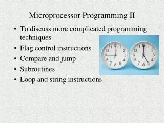
CPU Lecture 3 • CPU - is the section of the processor that processes the data by: • fetching instructions (from the program) stored in the memory, • decoding them and • executing them. • it consists of: • Control Unit • Arithmetic and Logic Unit (ALU) • Registers
CPU control unit Lecture 3 • The control unit controls the timing and sequence of operations • all actions within mP are synchronised to the CPU via a clock signal • clock signal = logic square wave to drive all the circuitry in the mP. Operations are reckoned in terms of the number of cycles they take. Typical clock frequencies: 1 to 30 MHz • timing signals are used to fetch program instructions from memory, to decode and to execute them
CPU control unit Lecture 3 • supplies control signals to: • read and write data into registers, • control ALU • and to control external control signals • CPU is responsible for the control of: • address, • data and • control buses • it acts as a 'master'
ALU Lecture 3 • arithmetic and logic unit - responsible for data manipulation • it performs: • arithmetic operations, such as add and subtract, and • logic operations (AND, OR, etc.) • it also performs: • bit shifting, • rotating, • incrementing, • decrementing and • testing
Registers Lecture 3 • Internal data that the CPU currently uses - stored in special memory locations on the CPU • These are called - registers • There are various types of registers • The number, size and types of registers used vary from one microprocessor to another • Some types are common and will be explained on the following slides
A selection of typical registers Lecture 3
Accumulator Register Lecture 3 • accumulator register - where data for the input to ALU is temporarily stored • First, the CPU needs to be supplied with the address of the required memory location where an instruction, or data, is stored so that it can access it via address bus • When this is done, the instruction, or data, is read into the CPU via data bus • Since only one memory location can be accessed at any one time, temporary storage has to be used when, for example, numbers have to be manipulated (added, subtracted etc.) • So, if 2 numbers are to be added, one number is fetched from its memory location and placed into an accumulator register while the CPU fetches the other number from another memory location • Once they are added to each other, the result is placed to the accumulator register for temporary storage
Flag register Lecture 3 • The flag register (or, status register, or condition code register) - contains the result of the latest process carried out by ALU • it contains individual bits, each having special significance. The bits are called flags. • The status of the latest operation is indicated by a flag • each flag may be set (e.I.1) or reset (e.I. 0) depending on the status
Program counter register Lecture 3 • It keeps track of the CPUs position in the program • it contains the address of the memory location of the next program instruction, hence the alternative name instruction pointer • as each instruction is executed, the program counter register is updated • the program counter is incremented each time so that the CPU executes instructions sequentially, unless some special commands (e.g. JUMP) are given to change it out of the sequence • not accessible by the programmer
Some other registers Lecture 3 • memory address register (MAR)contains the address of the data (like an 'address book' of all the addressed where various data are stored) • instruction register (IR) stores an instruction. After fetching an instruction from the memory, the CPU stores it in the IR. It can then be decoded and used to execute an operation • general purpose register - temporary storage for data or addresses; also for transfers between various other registers • stack pointer register (SP) - holds the address of the top of the stack in RAM. Stack - special area of RAM where program counter values can be stored when a subroutine of a program is being executed
Memory organisation Lecture 3
Memory organisation Lecture 3 • The memory unit stores binary data • The size of the memory is determined by the number of wires in the address bus • For data permanently stored - a read-only memory (ROM) device is used • If the content of ROM can be altered (somehow) it is referred to as erasable programmable ROM (EPROM) • Temporary data - I.e. the data currently being operated on - is stored in read/write memory called random-access memory (RAM) • When switched ON, the program from keyboard or other input device is loaded in RAM
Memory devices Lecture 3 • memory takes the form of an IC • the family tree of the memory devices is shown on the following tree-structure:
Memory devices Lecture 3 • typical EPROM: a series of small electronic circuits - cells - which can store charge. The program is stored by producing a pattern of charged/uncharged cells • The pattern is erasable using UV light (through a quartz window on the top of the device) • EEPROM is electronically erasable, which is easier - but, the chip itself is more expensive • Static RAM (SRAM) - based on bistable circuit. The output remains in its state until a subsequent valid input is issued. The bit cell of a SRAM is relatively large so it cannot be densely packed within a given area of silicon, which is a disadvantage
Memory devices Lecture 3 • The Dynamic RAM (DRAM) bit cell is a capacitor capable of storing charge. A single data line is used both to write data into the bit cell and to read data from it. The charge tends to leak out of the capacitor causing its voltage to drop, so DRAM needs to be periodically refreshed. This is why it is called 'dynamic' RAM. • Refreshing is done by reading data and writing it back to the same cell. • usually, circuitry external to the memory chip is used for refreshing • Packing density is higher for DRAMs than SRAMs, so more memory can be implemented in the given area. • Modern DRAM have their refresh control logic on-chip
Memory requirements Lecture 3 • there is a considerable difference in memory requirements between embedded and computing applications • in both classes the 'system memory' term is used to refer to the part which is directly accessible to the microprocessor, as opposed to the storage media such as a magnetic disc or tape drive etc. • in embedded systems, the memory consists of varying amounts of non-volatile memory (ROM), the contents of which will not be lost in the case of power loss, and volatile memory (RAM) which loses its content if power supply is removed. • Once information (program and constant data) is written into non-volatile memory it can be considered permanent and it is referred to as firmware
Memory requirements Lecture 3 • the programs in embedded systems are typically small. • For example, a washing machine control program may require only 2k bytes of memory. • For more demanding applications, such as communication controllers, several hundreds of kilobytes of ROM may be required
Input/Output Devices Lecture 3
Input/Output devices Lecture 3 • Input and output devices provide the means by which a microprocessor system can convey information between itself and the outside world. • Microprocesor has to accept input information, respond to it and produce output signals to implement required control • There may be inputs from sensors to provide data to the microprocessor and outputs such as relays or motors • The term peripheral is used for a device connected to a microprocessor. Such devices add specific functions, like timers and interrupt controllers to the mP system
Input/Output devices Lecture 3 • But, they cannot be, in general, directly connected to a microprocessor due to a lack of compatibility with the bus system in signal forms and levels • A circuit, called an interface, is used between the peripheral devices and the microprocessor to overcome this problem - to perform the required conversion • n general, I/O devices contain 2 types of registers: • control, or status register - through which the program can control the mode of operation of the I/O device • the second type of register provides the data path to enable the microprocessor system to read/write information to the outside world
Buses Lecture 3 • Data bus. To transfer the data associated with the processing function of the microprocessor. Word lengths may be 4,8,16 or 32 bits. Each wire in the bus carries a binary signal (0 or 1). The more wires the data bus has the longer the word length that can be used. Thus, for the word length of 4 bits, the number of values that can be transferred is 24=16
Buses Lecture 3 • Address bus which contains the address of a specific memory location for accessing stored data.It carries signals which indicate where data is to be found so that certain memory locations can be selected. When a particular address is selected by its address being placed on the address bus, only that location is open for communication with CPU. The CPU communicates with only one address at a time. Usually address bus contains 16 wires • Control bus. This carries the control signals to the memory and the I/O devices. It is used to synchronise separate elements. The system clock signal is carried by the control bus, for example.
Number representation - a brief reminder Lecture 3 • binary and hexadecimal number representations are commonly used in programming • to convert a binary number into a hexadecimal number it is handy to group digits in fours, because 24=16 and each block (of 4) can be represented by a single hexadecimal character • For example: a binary number 1011100100011110 grouped in fours gives: 1011 1001 0001 1110 B 9 1 E
Conversion table Lecture 3 Hexadecimal Decimal Binary 0 0 0 1 1 1 2 2 10 3 3 11 4 4 100 5 5 101 6 6 110 7 7 111 8 8 1000 9 9 1001 A 10 1010 B 11 1011 C 12 1100 D 13 1101 E 14 1110 F 15 1111
Memory mapping Lecture 3
Memory mapping Lecture 3 • The memory map designed to meet requirements of the application • It will be used by a hardware designer to partition the address space so that the address range of the memory devices in the system corrwsponds to the address range specified by the memory map • This is achieved my means of a address decoder • An example is shown in the following figures
RAM and decoder for 4k memory device Lecture 3
Chip Select signal Lecture 3 • when the correct address appears on the address bus the output from the decoding circuit changes to the logic state necessary to activate the device to supply/receive the data • the signal is called ‘Chip Select’ signal (CS/); often set as active low • a decoder is a combinational logic circuit which will decode a binary code and activate output signals according to the states of the lines applied at the input
Address decoder: logic gates Lecture 3
Address decoding Lecture 3 • let’s have a look at a typical 8-bit data bus whose wires (8) are numbered: D0 - first wire: least significant bit (LSB) D7 - eighth wire: most signif. bit wire (MSB) • and the 16-bit address bus (see Figure) • in the control bus there’ll be a line dedicated to READ/WRITE: • notation RD/ or WR/ (slash means active low) • a logic circuit decodes the address bus signal and selects the appropriate device
Address decoder: logic gates Lecture 3 • the least significant bit is at A12; it remains in a logic state '1' • A12 is passed through an inverter, so that the chip select signal at the output of the decoder is '0' only when A12 is '1' • note that in this case, the chip select signal is set to be 'active low', I.e. CS/ • similar decoding logic for each chip occupying the same amount of memory • if more complicated memory mapping is required, decoder functions are implemented using programmable logic array
Read/Write Cycles Lecture 3
Timing diagrams - read/write cycle Lecture 3 Figure 8.2
Read cycle Lecture 3 • It lasts 2 cycles of the clock signal: 1. address of required memory location put on address bus (by CPU), at rising edge 2. while device held at ‘tristate’ level - control bus issues ‘read signal’ (active low) to the device (2nd cycle begins) 3. after delay - valid data placed on data bus 4. levels on the data bus sampled by CPU at falling edge of the 2nd cycle
Write cycle Lecture 3 1.CPU places address at rising edge 2. decoding logic selects correct device 3. 2nd cycle - rising edge: CPU outputs data onto data bus & sets WRITE control bus signal active (LOW) • Note: • memory devices & other I/O components have static logic - so do not depend on clock signal; they read data from data bus when write signal high (inactive) - data must be valid for transition
A microprocessor system Lecture 3
Choosing a microprocessor systems Lecture 3 • the microprocessor system will be originally conceived from a functional requirement. For example, to control a robot arm, or to monitor some process etc. • based on the requirements the system specification will be made Input/Output requirements • the number and type of input/output devices will be based on the number of sensors and actuators needed for the function • communications with other systems in order to provide remote control will be chosen to be compatible with these systems in terms of both hardware and protocols used
Choosing an mP system Lecture 3 • complexity of the function to be performed will influence the choice of the processor, the CPU in particular • performance is the most critical factor to be considered and most difficult to assess • number of operations per second IS NOT a sufficiently good indicator of the performance • benchmarking is better - running a representative piece of code to determine the speed of execution • simulator is another good way of assessing the performance
Development environment Lecture 3 • the set of tools with which the designer can verify the hardware design , write and test the software and test the complete system are presented in the figure below
A microcontroller & various peripherals Lecture 3
Development environment Lecture 3 • the prototype hardware is referred to as target system • the software for the target system is written on a computer referred to as the host as it hosts the development tools during the development (nowadays, it is usually a PC) • when the program functions correctly it may be programmed into a ROM device and be permanently installed on a target system • the interface between the host and the target system is a hardware emulator for the target microprocessor. It has the ability to control the execution of the application program • typically, the emulator is a standalone unit
Development environment Lecture 3 • alternatively, emulator can be an add-in card to the personal computer (the host) • communication link is usually a simple serial RS232 interface • through that link the host downloads the machine code application program to the emulator and controls and monitors its execution • to the target system emulator appears as would the real microprocessor
Development cycle Lecture 3 • there is a well defined development cycle typical of any product development • The basic cycle is shown schematically in the following diagram: First design Implement design Test design against the spec. Does it meet specifications? Review design Manufacture a product No Yes
Development cycle Lecture 3 • the designer enters the application program into the host system using an editor (similar to a word processor). The programming language can be either a high-level (e.g. C) or a low-level (assembler) language • the next step is to convert the source code into the machine code instructions understood by a specific microprocessor. This is done by a language compiler or by an assembler, depending on which language has been used • the output of a compiler will be a file containing the machine code, which when executed by the target microprocessor will perform the functions defined by the source code. This machine code is called object code