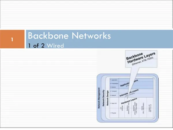
Backbone Networks
Backbone Networks. Chapter 7. Backbone Network Components. There are two basic components to a backbone network: The network cable - essentially the same as used in LANs, except it is usually higher quality to provide higher data rates.

Backbone Networks
E N D
Presentation Transcript
Backbone Networks Chapter 7
Backbone Network Components There are two basic components to a backbone network: • The network cable - essentially the same as used in LANs, except it is usually higher quality to provide higher data rates. • The hardware devices that connect other networks to the backbone - special purpose devices and computers that just transfer messages from one network to another.
Backbone Network Devices Physical Data Link Network Device Operates at Messages Layer Layer Layer Hub Physical All transferred S/D Same Same Bridge Data link Filtered using S/D Same Same data link layer add. Switch Data link Switched using S/D Same Same data link layer add. Router Network Routed using S/D S/D Same network layer add. Gateway Network Routed using S/D S/D S/D network layer add.
Bridges Bridges operate at the data link layer. They connect two LAN segments that use the same data link and network protocol. They may use the same or different types of cables. Bridges “learn” whether to forward packets, and only forward those messages that need to go to other network segments.
Bridges If a bridge receives a packet with a destination address that is not in the address table, it forwards the packet to all networks or network segments except the one on which it was received. Bridges are a combination of both hardware and software, typically a “black box” that sits between the two networks, but can also be a computer with two NICs and special software.
Switches Like bridges, switches operate at the data link layer. Switches connect two or more computers or network segments that use the same data link and network protocol. They may connect the same or different types of cable. Switches operate at the same layers as bridges but differ from them in two ways: • First, most switches enable all ports to be in use simultaneously, making them faster than bridges. • Second, unlike bridges, switches don’t learn addresses, and need to have addresses defined. Example: Intel Express 510 T switch.
Switches There are two types of switches: Cut-through switches examine the destination of the incoming packet and immediately connect the port with the incoming message to the correct outgoing port. It is hardware-based. Store-and-forward switches copy the incoming packet into memory before processing the destination address.
Routers Routers operate at the network layer. Routers connect two or more LANs that use the same or different data link protocols, but the same network protocol. Routers may be “black boxes,” computers with several NICs, or special network modules in computers. In general they perform more processing on each message than bridges and therefore operate more slowly.
Routers vs Bridges • Routers can choose the best route. • Routers also only process messages specifically addressed to it. • Routers can connect networks using different data link layer protocols. Therefore, routers are able to change data link layer packets. • Routers may split a message into several smaller messages for transmission.
Layer 3 Switches • Problems With Layer 2 Switches • Broadcast overload because of the single MAC broadcast address (e.g. using ARP for Data Link Layer address resolution) • Lack of multiple links - only one path • Normally, the above problems can be solved with several subnets connected by routers. However, • A MAC broadcast frame is then limited to only the devices and switches contained in a single subnet. • A router does all IP-level processing, some of which could be not necessary. • It is implemented in software and slow. • Layer 3 switches implement the packet-forwarding logic of the router in hardware. • Packet-by-packet • Flow-based
Gateways Gateways operate at the network layer and use network layer addresses in processing messages. Gateways connect two or more LANs that use the same or different (usually different) data link and network protocols. The may connect the same or different kinds of cable. Gateways process only those messages explicitly addressed to them.
Gateways Gateways translate one network protocol into another, translate data formats, and open sessions between application programs, thus overcoming both hardware and software incompatibilities. A gateway may be a stand-alone microcomputer with several NICs and special software, a FEP connected to a mainframe computer, or even a special circuit card in the network server.
Gateways One of the most common uses of gateways is to enable LANs that use TCP/IP and ethernet to communicate with IBM mainframes that use SNA. The gateway provides both the basic system interconnection and the necessary translation between the protocols in both directions.
A Caveat The terminology used in the marketplace may differ substantially. One vendor’s bridge may provide the functions of a router. • Multiprotocol routers -can understand several different network layer protocols. • Brouters – Combine the functions of both bridges and routers. They operate at both data link and network layers. • Layer-3 switches (IP switches) - can also switch messages base on their network layer address. They can be used in the place of routers, but faster.
Backbone Network Architecture LAN LAN LAN LAN LAN LAN Distribution Layer Access Layer Core Layer Figure 7-5 Backbone network design layers
Backbone Network Architectures • Routed backbone – using routers • Advantage – clearly segment each part of the network • Disadvantage – Delay, and more management • Bridged backbone – using bridges, not popular any more • Advantages – cheaper, simpler • Disadvantages – difficulties in management • Collapsed backbone –using switches, is most commonly used. • Advantages - Better performance, Fewer network devices are used • Disadvantages – switch problem may fail whole network, more cabling work • Two types • Rack-based collapsed backbone • Chassis-based collapsed backbone • Virtual LAN (VLAN)
Client Computer Client Computer 10/100 Ethernet Client Computer Router to WAN Layer-2 Switch Client Computer 1GbE on fiber Client Computer 1000Base-T Client Computer Layer-3 Switch 10/100 Ethernet Router to Internet Client Computer 1GbE on fiber 1GbE on fiber Client Computer 10/100 Ethernet Client Computer Layer-2 Switch Client Computer Server Server Client Computer 1000Base-T Server Server Client Computer Figure 7-11 Central Parking’s collapsed backbone
Virtual LAN (VLAN) • A new type of LAN backbone network architecture by intelligent high-speed switches. VLAN is configured using software not hardware. • Single-switch VLAN – VLAN inside a switch • Multiswitch VLAN – VLAN using several switches. • VLAN is normally faster than traditional LANs, and provide better opportunity to manage data flows
VLAN switch Client Computer VLAN switch VLAN switch Client Computer 10/100 Ethernet Client Computer VLAN switch VLAN switch Client Computer 1GbE on fiber Client Computer 1000Base-T Client Computer VLAN switch 1GbE on fiber VLAN switch VLAN switch VLAN switch 1GbE on fiber VLAN switch VLAN switch VLAN switch 1GbE on fiber VLAN switch VLAN switch VLAN switch VLAN switch VLAN switch Figure 7-14 IONA VLAN network
Backbone Technologies • Fiber-Distributed Data Interface (FDDI) • Asynchronous Transfer Mode (ATM) • Fibre Channel
Fiber Distributed Data Interface (FDDI) Fiber Distributed Data Interface (FDDI) is a set of standards originally designed in the late 1980s for use in MANs (ANSI X3T9.5), but has since made its way into backbone networks. FDDI is a token-passing ring network that operates at 100 Mbps over two-counter-rotating fiber optic cable rings.
Topology The FDDI standard assumes a maximum of 1000 stations and a 200-kilometers (120 miles) path that requires a repeater every 2-kilometers. The second ring is for backup. Single attachment stations (SAS) and dual-attachment stations (DAS) are both computer that can connect to one or both of the rings, respectively. If the cable in the FDDI ring is broken, the ring can still operate in a limited fashion.
Media Access Control The FDDI-MAC scheme uses a variation of the IEEE 802.5 token-passing standard. • Messages and the token are sent in different frames separately in a FDDI LAN. A computer can send data only when it captures the token. • When a computer on an FDDI network waiting for transmission receives the token, it holds the token and then transmits all messages that were attached to it. The computer then transmits whatever messages its wants before transmitting the token. • When receiver receives the data frame it simply copy the data frame leaving it to be absorbed by the sender.
Switched FDDI Switched FDDI is similar to switched Ethernet, in that a FDDI switch replaces the FDDI hub, providing a series of point-to-point connections from the computers to the switch instead of the traditional shared circuit. The network has a star topology instead of a ring, and no token. It does use the FDDI packet format and is fully compatible with other FDDI hardware.
Asynchronous Transfer Mode (ATM) Asynchronous Transfer Mode (ATM) (a.k.a. cell relay) is a technology originally designed for use in wide area networks that is now often used in backbone networks. ATM backbone switches typically provide point-to-point full duplex circuits at 155 Mbps (total of 310 Mbps).
Asynchronous Transfer Mode (ATM) ATM is a switched network but differs from switched Ethernet and switched token ring in four ways: 1. ATM uses fixed-length packets of 53 bytes. 2. ATM provides no error correction on the user data. 3. ATM uses a very different type of addressing from traditional data link layer protocols such as ethernet or token ring. 4. ATM prioritizes transmissions based on Quality of Service (QoS).
Addressing & Forwarding with ATM Virtual Circuits Address format: Virtual circuit identifier = (path#, circuit#)
Asynchronous Transfer Mode (ATM) ATM is connection-oriented so all packets travel in order through the virtual circuit. A virtual circuit can either be a: • Permanent Virtual Circuit (PVC) - defined when the network is established or modified. • Switched Virtual Circuit (SVC) - defined temporarily for one transmission and deleted with the transmission is completed.
ATM Classes of Service • Constant Bit Rate (CBR) • Originally for voice transmission • Variable Bit Rate--Real Time (VBR-RT) • Switch immediately upon receiving a packet • Variable Bit Rate--Non-Real Time (VBR-NRT) • Available Bit Rate (ABR) • Unspecified Bit Rate (UBR)
ATM and Traditional LANs Edge switches translate LAN packets to ATM cells to enable the packets to flow over the ATM backbones. Two approaches: • LAN encapsulation (LANE, a.k.a. LAN Emulation) • Multiprotocol over ATM (MPOA). Address translation from Ethernet or token ring into ATM is not simple - ATM lacks a simple built-in ability to issue broadcast messages.
How LANE Works Step 1: Translate the Ethernet address into an ATM virtual circuit identifier for the circuit that leads from the edge switch to the edge switch nearest the destination. Step 2: Find the virtual circuit address for the destination data link layer address. Step 3: Break the LAN packet into the series of ATM cells, and transmit them over the ATM backbone using the ATM virtual circuit identifier.
ATM and Traditional LANs The process of LAN-ATM packet conversion can cause quite a delay (a throughput reduction of 40 to 50 %). MPOA is an extension to LANE being able to handle network layer addresses. ATM backbone works like a brouter. If a packet is addressed to a different subnet, MPOA will use the network layer address to forward the packet.
Fiber Channel Network N_port F_port
Fibre Channel Elements • Nodes • The end systems • Includes one or more N_ ports for interconnection • Fabric • Collection of switching elements between systems • Each element includes multiple F_ ports • Responsible for buffering and for routing frames between source and destination nodes
Full-duplex links with two fibers per link Performance from 100 Mbps to 800 Mbps on a single link (200 Mbps to1600 Mbps per link) Support for distances up to 10 km Small connectors High-capacity utilization with distance insensitivity Greater connectivity than existing multidrop channels Broad availability (i.e., standard components) Support for multiple cost/performance levels, from small systems to supercomputers Ability to carry multiple existing interface command sets for existing channel and network protocols Fibre Channel Goals
*Fibre ChannelProtocol Architecture • FC-0 Physical Media: Includes optical fiber, coaxial cable, and shielded twisted pair, based on distance requirements • FC-1 Transmission Protocol: Defines the signal encoding scheme • FC-2 Framing Protocol: Defines topologies, frame format, flow/error control, and grouping of frames • FC-3 Common Services: Includes multicasting • FC-4 Mapping: Defines the mapping of various channel and network protocols to Fibre Channel
Fibre Channel - Maximum Distance 800Mbps 400Mbps 200Mbps 100Mbps Single Mode 10,000m 10,000m 10,000m 10,000m M-mode 500m 1,000m 2,000m -- Coaxial Cable 50m 71m 100m 100m STP 28m 46m 57m 80m