Download
1 / 29
730 likes | 2.73k Vues
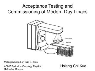
ERECTION AND PRE COMMISSIONING TESTING OF EQUIPMENTS. BY Y.SURYA PRAKASA RAO Chief Manager. Receipt at site

E N D
ERECTION AND PRE COMMISSIONING TESTING OF EQUIPMENTS BY Y.SURYA PRAKASA RAO Chief Manager
Receipt at site • After Receipt at site and before unloading the materials ,the conditions of packing and record of the transportation shall be jointly assessed by owner and contractor and dully recorded.
Unloading and storage at site Unloading Unloading of materials should be done with crane of suitable capacity using polyester slings only.
Storage at site Storage instructions should be followed strictly as per storage instructions in equipment manual. While shifting materials from storage place to final place for erection, sufficient care is to be taken to avoid damage to the materials. The material shall be opened after reaching the place of erection . In case the material is found damaged during storage and shifting. Inform supplier, erection contractor and Insurance agency.
Storage at site LA should be stored vertically. CVT should be stored vertically. CT should be stored vertically or if it is horizantal, keep around 30 degree height at top side. WT should be stored vertically. Store all equipments above ground level by making platforms.
ERECTION OF EQUIPMENTS 1. MEASURE FOUNDATION BOLTS DISTANCE & LEVELING. 2. CHECK THE BASE PLATE HEIGHT WITH EXISTING EQUIPMENT BASE PLATE. 3. CHECK THE LEVELING OF STRUCTURE AT TOP WITH SPIRIT LEVEL AND TIGHT ALL NUTS & BOLTS. 4. ERECT EQUIPMENT PREFERABLY WITH CRANE AS PER MANUFACTURER RECOMMENDATIONS.
ERECTION OF EQUIPMENTS 5. ERECT THE CT PRIMARY POINTS P1 & P2 AS PER DRAWING. 6. ERECT LAS BY KEEPING VENTS DIRECTION AWAY FROM EQUIPMENTS. 7. ERECT ISOLATOR EARTH SWITCH POSITION AS PER DRAWING.
PRE COMMISSIONING TESTS OF CT 1.POLARITY TEST. 2.MAGNETISATION CHARACTERISTICS OF CT. 3. RATIO TEST. 4.IR MEASUREMENT. 5. DGA TEST OF OIL. 6. TANDELTA & CAPACITANCE MEASUREMENT.
PRE COMMISSIONING TESTS OF CVT 1.POLARITY TEST. 2. RATIO TEST. 4. IR MEASUREMENT. 5. TANDELTA & CAPACITANCE MEASUREMENT
PRE COMMISSIONING TESTS OF SA 1. THIRD HORMONIC RESISTIVE CURRENT. 2. IR MEASUREMENT OF INDIVIDUAL STACK. 3. OPERATION OF LA COUNTER. 4. TANDELTA & CAPACITANCE MEASUREMENT
PRE COMMISSIONING TESTS OF ISOLATOR 1. MILLIVOLT DROP TEST. 2. IR MEASUREMENT . 3. 50 OPERATIONS TEST.
CONSTRUCTION FEATURES. Circuit Breaker is an on load Switch which can make & break load currents and fault Currents in shortest time. What it requires ?1.Support Structure.2. Operating Drive Assembly.3.Pole Column.4.Interrupter.5.Control Cubicle.
SUPPORT STRUCTURE • Lattice structure or Tripod. • It carries the operating drive assembly,pole column and Interrupter . • It will stand on the concrete foundations.
OPERATING DRIVE ASSEMBLY It consists … • Pneumatic/hydraulic operating mechanism. • Compressor-motor/hydraulic pump. • Air-reservoir/ hydraulic reservoir. • Linkage mechanism. • Auxiliary switches.
POLE COLUMN It consists… • Stacks of support porcelain Insulators to insulate the live parts from the ground. • Operating rod(Insulating rod) with guiding rings transmits movement from driving assembly to moving contacts. • SF6 gas . • Shaft seal assembly seals the SF6 gas.
INTERRUPTER ASSEMBLY • Closing resistor assembly(optional)-400 ohms. • Grading capacitors(oil filled) -1200 PF .
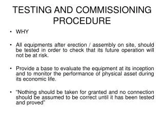
TESTS • Pre-commissioning Tests.
PRE-COMMISSIONING TESTS • Pressure Switch settings of SF6 gas&Air/Oil. • Air/Oil Pressure drop tests during operation. • Air/Oil&SF6 gas Leakage tests in 24hrs. • Pole Discrepancy test for open/close. • Dew point & Air content tests for SF6 gas. • Milli volt drop test in close position. • Capacitance&Tan delta test for Grading Capacitor. • Operation timings test. • Insulation Resistance measurement tests.
ROUTINE MAINTENANCE TESTS • SF6 gas&Air/Oil Pressure Switch settings. • Air/Oil Pressure drop tests during operation. • Pole Discrepancy test for open/close. • Operation timings test. • Dew point for SF6 gas. (Two yearly) • Milli volt drop test in close position.(Two yearly) • DCRM & Contact Travel Measurement tests.(Three yearly) • Capacitance&Tan delta test for Grading Capacitor.(four yearly)
OPERATION TIMINGS • Close timings including PIR. • Trip 1 timings . • Trip 2 timings. • Close Trip for both Trip 1 &2. • Duty cycle operation times(O-0.3s-CO). • Pole discrepancy time during open&close.
ACCEPTABLE/PERMISSIBLE LIMITS FOR MAINTANANCE TEST RESULTS. • CB operation timings.400kv220kv • -Closing time(max) 150Ms 200Ms • -Trip time(max) 25Ms 35Ms • -Close/Trip time • pole Discrepancy • phase to phase(max) 3.33Ms 3.33Ms • Break to Break(max) • of same phase 2.5Ms 2.5Ms
PIR TIME • BHEL make 12-16ms • CGL make 8-12ms • ABB make 8-10ms • NGEF make 8-12ms • M&G make 8-12ms • TELK make 8-12ms • ABB make(HVDC) 8-12ms
PIR opening time prior to opening of main • contacts(ABB.CGL.NGEF make CBx) . 5ms(min) • AT RATED PRESSURE • PIR and main contacts overlap time • (BHEL,M&G,ABB imported)make CBx). 5ms(min) • AT RATED PRESSURE • TAN DELTA of grading capacitors 0.007degrees at 20deg.cel. • Capacitance of grading capacitors within +10 of the rated value • within –5 • Contact resistance of CB 150 micro-ohm • Contact resistance of CB terminal • Connector 10micro-ohm per connector
IR value: • Phase earth100m-ohm(min) by 5.0/10.0kvMEGGER • Across open contacts 1000m-ohm (min) by 5.0/10.0kvMEGGER • Control cables 50m-ohm(min)by 0.5kv MEGGER • PRESSURE SWITCH SETTINGS • SF6 gas pressure switches within 0.1BAR OF SET VALUE • Operating air pr.switches within 0.1BAR OF SET VALUE • Operating oil pr.switches within 1.0 BAR OF SET VALUE
DEW POINT OF SF6 GAS Make of CBDew point at CorrespondingRemarks rated pr.Dew pt.at atmo.pr. BHEL -15deg.cel. -36deg.cel. During commissioning -7deg.cel. -29deg.cel. During O&M -5deg.cel. -27deg.cel. Critical M&G -39deg.cel During commissioning -32deg.cel. During O&M CGL -15deg.cel. -35deg.cel. During commissioning -10deg.cel. -31deg.cel. During O&M ABB -15deg.cel -35deg.cel. During commissioning-5deg.cel -26deg cel. During O&M NGEF -15deg.cel -36deg.cel. During commissioning -7deg.cel. -29deg.cel During O&M -5deg.cel -27deg .cel. Critical