Download
1 / 46
480 likes | 962 Vues
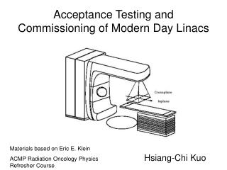
Acceptance Testing and Commissioning of Modern Day Linacs. Materials based on Eric E. Klein ACMP Radiation Oncology Physics Refresher Course. Hsiang-Chi Kuo. CONTRACT ISSUES. Get Involved with Contract If Contract Mentions ATP, Review ATP If any Specification is Missing or Deficient

E N D
Acceptance Testing and Commissioning of Modern Day Linacs Materials based on Eric E. Klein ACMP Radiation Oncology Physics Refresher Course Hsiang-Chi Kuo
CONTRACT ISSUES • Get Involved with Contract • If Contract Mentions ATP, Review ATP If any Specification is Missing or Deficient Have it Changed • Be Specific on Equipment and Staffing Needs to Vendor and Administrator.
CONTRACT ISSUES • Understand Clinical Needs (i.e. tighter gantry specs. If stereo is to be performed). • Ask for specifics on timing, considering the potential for problems. • Ask for warranty and maintenance specifics. • Ask about training provided by vendor.
LINAC SAFETY (AAPM TG-35) • Radiation Warning Signs (check state regs.) • Warning Lights (location and conditions) • Emergency Off buttons and locations • Door Interlocks • Emergency Power • Radiation Safe Location for modulator cabinet • Audio/Video (and backup) • How room lights and lasers function 緊急關閉按鈕 Emergency-off switch 安全功能正常 安全性連鎖(含門、緊急停止與臨時中斷) Safety interlock 安全功能正常 區域監測器 Area monitor 安全功能正常
LINAC SAFFTY Interlocks • Dose machine recover from a hard crash (power loss or emergency off)? • Try to simulate console operation mistake • Do all backup systems work (maximum time, MU, FS for wedges.) • Anti-collision checks (e-applicators) • Couch locks, support, maximum weight, travel • Retractable beam stop (or image device) - travel time, interlocks for gantry angle and FS. 電子錐筒連鎖 electron cone interlock 安全功能正常
TIME REQUIREMENTS • ABR manpower survey of 1995 quoted 350 hours (median) for AT/Commissioning of a dual-energy/electron linac. This included energy and confirmation of TP and MU table data. • This linac time did not include MLC, asymmetric jaws, dynamic wedge, or portal imaging. (Might take an additional 60-80 hours.) • The time did not include special procedures.
TIME REQUIREMENTS – Special Procedures (ACMP) study • TSET – 105 hours (median) • TBI – 85 hours • Linac Stereotactic Radiosurgery – 200 hours • Intraoperative Radiotherpy – 255 hours • Electron Arc – 413 hours • IMRT (Peacock) > 200 hours (MIR) • DMLC > 200 hours (MSKCC)
EQUIPMENT NEEDS • Scanning System, Water and Film -Multi-Array Measurement System (diodes, chambers) • Torpedo Level • Standard ADCL Electrometer/Chamber • At least 100 XTL or EDR films • Micro-chambers and/or Film Laser Scanner (aperture < 0.1mm) for MLC penumbra, etc.
RADIATION SAFETY • At First Beam-on, a Cursory is Performed • Following Calibration, a Formal Survey is Performed to all Locations, combined with all scenarios (IMRT, TBI, TSET) • Collimator Jaw Transmission (<0.5%) • Place Film over Fiberglass to ascertain leakage hot spot • Place Ion Chamber 1m from Source Along Hot Spot Plane to Ensure Leakage < 0.1% • Measure Neutron within and outside of room, combining contributions with photon leakage.
Neutron Detectors • Neutrometer (Apfel, 1981) showing 32 bubbles after exposure to approximately 6 millirem (60 uSv). 5 bubbles/mrem, 50 bubbles max. • Neutron rem meter; BF3 proportional counter in 9” Cadmium-loaded polyethylene sphere, operates at 1600~2000 V, and detects neutrons from thermal to ~10MeV.
MECHNICAL CHECKS • Collimator Rotation: Rotate the collimator with a pointer at isoc. And graph paper. Ensure run out <1mm radius. • Gantry Rotation: Attach pointer onto couch (drill bit). Rotate gantry and ensure run out <o.5mm. • Table Rotation: Rotate the table with a pointer at isoc. And graph paper. Ensure run out <1mm radius. 十字交叉線中心位置 Cross-hair centering 機械直徑2mm以內 準直儀機械旋轉中心 Collimator mechanical isocenter 機械直徑2mm以內 旋轉臂機械旋轉中心 Gantry mechanical isocenter 機械直徑2mm以內 治療床機械旋轉中心 Couch mechanical isocenter 機械直徑2mm以內
LIGHT FIELD ALIGNMENT AND CALIBRATION • Verify cross-hair intersect mechanical isoc. And are parallel with jaw projections (±1mm) • For symmetric and independent jaw settings confirm digital display is with 1mm of light projection for range of FS. Ensure room is dark and graph paper is accurate 照野指示器 Field size indicators 機械 ±2mm或±1%的照野 準直儀對稱性 Collimator symmetry 機械 ±2mm
Angle Readouts • Collimator: Set Gantry to 180º. Rotate the collimator CW and CCW 90º, marking cross-hair projection onto graph paper. Ensure digital and mechanical readouts are within 0.5º and 1.0º. • Gantry: Using spirit level, find the “cardinal” angles (0, 90, 180, 270). Ensure digital and mechanical readouts are within 0.5º and 1.0º. 旋轉臂﹑準直儀角度指示器 Gantry,collimator angle indicators 機械 ±1度
COUCH MOTIONS • Rotation: Check Mechanical and Digital Readouts at “cardinal” couch angles. Ensure digital and mechanical readouts are within 0.5º and 1.0º. • Vertical: Check with couch at isoc. And at lowest position. Use ruler to record table increments. Ensure readouts are within 2mm. • Lateral: Over range of ±25cm, ensure readouts are within 2mm. • Longitudinal: Over range of ±60cm, ensure readouts are within 2mm. 治療床垂直升降的直線性 Alignment of vertical travel of couch 機械±2%
ODI and DISTANCE INDICATORS • Ensure front pointers are accurate and consistent to ±1mm. • Check ODI from 70 to 156 cm. Ensure accurate TSD readings are within ±1mm. (Spot check at “cardinal” gantry angles for 100cm. • It is also advisable to record distances in room such as floor to isoc., minimum table position, etc. 光學距離指示器 ±2mm
RADIATION ISOCENTER • Gantry Rotation: Close lower jaws to 1cm width. Rotate about isocenter and expose at select angles. Biset with sharp line. Ensure maximum excursion is 1mm. 0º Area of Interest 90º
RADIATION ISOCENTER • Collimator, Couch Rotation: Close lower jaws to 1cm width. Rotate about isocenter and expose at select angles. Biset with sharp line. Ensure maximum excursion is 1mm. 準直儀輻射旋轉中心 Collimator radiation isocenter 機械直徑2mm以內 旋轉臂輻射旋轉中心 Gantry radiation isocenter 機械直徑2mm以內
LIGHT AND X-RAY COINCIDENCE • For all energies and for range of field size; - Ensure you have film (flat and without air pockets) at isocenter. - Etch each illuminated field (dark room) at edges with small pin. • Coincidence must be within 2mm. • Spot check at cardinal gantry angles. 光與輻射照野一致性 Light/radiation field coincidence 機械 ±2mm或±1%照野
PHOTON BEAM PERFORMANCE • Flatness: 10x10 and 40x40 cm2 at 10 cm depth - For all energies in both planes (transverse, radial) - Variation of intensity (max. to min.) shall not exceed ±3% of mean over 80% of field as defined by FWHM. - Spot check at dmax depth. • Symmetry: Same setup - Variation shall not exceed 2% 光子平坦性穩定度 Photon flatness constancy 劑量±2% 光子對稱性穩定度 Photon symmetry constancy 劑量±3%
PHOTON ENERGY • Depth of dmax shall be within 2 mm of BJR values. • Intensity at 10 cm shall be within 2% (hv<15MV) or 1% (hv>15MV) of BJR values. Energy Dmax depth %DD at 10 cm 6MV 1.5cm 67% 15MV 2.9 cm 77% 光子中心軸百分深度劑量比 Photon central axis PDD constancy 劑量±2% 光子射束中心軸於治療深度之劑量參數 Photon central axis dosimetry parameter constancy 劑量±2%(點測量)
ELECTRON BEAM PERFORMANCE • Flatness: 10x10 and largest applicator at calibration depth (ICRU-35) - For all energies in both planes (transverse, radial) - Variation of intensity (max. to min.) shall not exceed ±5% of mean over 80% of field as defined by FWHM. • Symmetry: Same setup - Variation shall not exceed 2% 電子平坦性穩定度 Electron flatness constancy 劑量±3% 電子對稱性穩定度 Electron symmetry constancy 劑量±3%
ELECTRON ENERGY • Varian specifies according to ICRU-35 values. • Depth of 80% shall be within 1mm. • Depth of 30% shell not exceed specified depth. Energy Depth (cm) of Max. depth (cm) (MeV) 80% intensity of 30% intensity 6 MeV 1.90 2.6 12 MeV 4.15 5.4 20 MeV 6.55 9.3 電子中心軸百分深度劑量比穩定度 electron central axis PDD constancy 劑量±2% 電子射束中心軸於治療深度之劑量參數 Electron central axis dosimetry parameter constancy 劑量±2% or ±2mm(在治療深度內)
ELECTRON BEAM (X-RAY CONTAMINTION) • Examine percent intensity curves. • For scatter-foil beams, ensure that intensity is < 5% of max. intensity, 10 cm beyond 10% value. 100 % Intensity <5% 10 cm 10 Depth
OUTPUT STABILITY • Short term reproducibility: 3 consecutive readings shall be consistent within 1%. Check output daily during AT and Commissioning to be within 2%. • Long term reproducibility. • Spot check for low and high MU settings, and for cardinal gantry angles. • Ensure rep rates are accurate, by limiting time. 監測游離腔之線性 Monitor chamber linearity 劑量±2%
DYNAMIC ARC PHOTONS • For Varian accelerators, MU delivered shall be within 0.2 MU, stop angle within 0.5º. (View STT) • Test for various clinical ranges, where MU/deg set equals MU/deg delivered for CW and CCW. • Recommend taking ionization measurements at isocenter within cylindrical phantom. • Check software and dosimetry for interrupted treatment.
SPECIAL PROCEDURES • TBI: Test Operation in special TBI mode for maximum MU and Dose Rate. Measurements can be made at isocenetr to compare with conventional therapy. • HDTSET: Test Operation in Special mode for maximum MU and Dose Rate. Measurements can be made at isocenter to compare with conventional therapy. In addition, symmetry between field halves must be within 2%. • Electron arc: MU delivered shall be within 0.2 MU, stop angle within 0.5º.
ELECTRON APPLICATORS • Check interlocks and jaw setting for each energy. • Check centering. Ensure centering is maintained at lateral gantry angle, with cerrobend insert. • Check for leakage/transmission through applicator sides. • Check for cerrobend insert stability with gantry rotation. 電子錐筒連鎖 electron cone interlock 安全功能正常
MLC: Interlocks • Automatic Retraction: Leaves should retract when MLC mode is completed or an electron applicator is inserted. • Gap behind leaves. For tertiary system, back edge of leaves must be covered by collimating jaws. • Test file compatibility by trying to drive a field with a leaf set to a unobtainable position.
Record and Verify Systems • Ensure accelerator readouts are being read properly. • Ensure interrupted treatments are recorded properly. • Ensure auto-setup functions are safe and accurate. • If R&V drives MLC, ensure all MLC interlocks operate properly. • Check all accelerator at extreme conditions - i.e. an extreme table position may not be within R&V’s limits - maximum MU for special procedure.
DYNAMIC WEDGE • Check STT printouts (software) to ensure that jaw and MU are delivered at intended to within 0.2 MU and 1.5 mm. Check for both directions. • Spot Check WFs. • Test that interrupted delivery gives the same composite distribution as a complete run. • Setup morning checkout DW runs. 楔形濾器 Wedge interlock 安全功能正常
MILTILEAF COLLIMATION • One must first decide how leaves are to be calibrated. Most system will be specified to have the leaf position (readout) correspond with the light field. If this is acceptable, be aware that that the 50% radiation will not exactly correspond with leaf position. • Try to force calibration of leaf positions to correlate with 50% radiation edge. • Actual difference is less than 2 mm.
MLC: Leaf Positioning • Check leaf positions for each carriage at intervals of -15 cm to 40 cm in steps of 5 cm. Accuracy shall be within 1 mm. Check for reproducibility. • Coincidence of light and radiation shall be within 2 mm. Check for small and large field sizes. • Spot check positioning at cardinal gantry angles.
MLC: Radiation Tests • Collimator Spoke Shot: Close leaves to make a 1 cm field width and expose film at various collimator angles. Bisect strips with thin lines and ensure the lines intersect to within 1 mm. • Gantry Spoke Shot: Close leaves to make a 1 cm field width and expose film at various gantry angles. Bisect strips with thin lines and ensure the lines intersect to within 1 mm.
MLC: Radiation Tests • Interleaf Transmission: - First take open field reading with leaves retracted. - Take readings under each carriage with leaf abutment placed as far away as possible. Find maximum transmission point. • Abutted leaf Transmission: No specification. But if leaves are set to touch, ensure transmission <50%. 穿透因子穩定度 Transmission factor constancy 劑量±2%
MLC: Radiation Tests • Interleaf Transmission: - First take open field reading with leaves retracted. - Take readings under each carriage with leaf abutment placed as far away as possible. Find maximum transmission point. • Abutted leaf Transmission: No specification. But if leaves are set to touch, ensure transmission <50%.
MLC: Shaping Software • Test simple cases such as squares. Digitized shape and leaf position should be within 1 mm. • Save file(s) onto floppy and transfer to MLC workstation. • Verify MLC will enter Treat mode and pattern is as expected within 1 mm. • Check edit capabilities, ensuring new files are created.
COMMISSIONING • Majority entails clinical data needs. - Monitor unit calculations; depends on algorithm. - Treatment Planning Data • Special Calculations - Surface dose - Extended treatment distance • Special Procedures - TBI, Stereotactic, TSET, etc.
COMMISSIONING – OUTPUT FACTORS • ADCL Calibration inter-compared with monthly review system and daily check system. • Acquire Collimator Scatter Factors – in air. High-density caps or calibrations for small fields. • Acquire Peak Scatter Factors. • Decipher output factors for MLC, alloy and asymmetric jaw field shaping. • Measure OF for electrons for each cone and SSDs to be used. 光子照野因子穩定度 Photon field size factor constancy 劑量±2% 電子錐因子穩定度 Electron cone factor constancy 劑量±2%
COMMISSIONING – Wedges • Wedge Factors for physical wedge. - Tabulate FS and depth dependence, which can be taken from PDD scans for wedges. - Acquire off-axis wedge factors from profile scans. • Dynamic wedge factors - Tabulate FS dependence (Varian – related to fixed jaw value). - Acquire off-axis WF from STT tables. 楔形濾器穿透因子穩定度 Wedge transmission factor constancy 劑量±2%
COMMISSIONING – Depth Dose • Photon Beam - Range of FS for TP. May need to scan with diodes or micro-chamber for small fields. - Acquire DD scans for physical wedges and spot check PDD for dynamic wedges. - Various SSDs may be needed for TP system. • Electron Beam - For range of FS. Spot check at extended SSDs. 光子/電子中心軸百分深度劑量比穩定度 Photon/electron central axis PDD constancy 劑量±2%
COMMISSIONING – Profiles • Acquire profiles as needed for TP, i. e. 4x4 to 40x40 cm2 in transverse and longitudinal planes, for range of depth for open and phys. Wedge photon fields. In addition acquire diagonal scans at dmax. • Dynamic wedge profiles can be acquired can be acquired with film or array devices. • Electron Beam - For all applicators and at required depths. - Require multiple SSDs. 光子平坦性穩定度 Photon flatness constancy 劑量±2% 電子平坦性穩定度 Electron flatness constancy 劑量±3% 光子對稱性穩定度 Photon symmetry constancy 劑量±3% 電子對稱性穩定度 Electron symmetry constancy 劑量±3%
COMMISSIONING – OFF-AXIS RATIOS • Decide on method for calculating points away from central axis, typically off-center ratios (depth). • Decide method to correct for heavily blocked and asymmetric fields, typically requiring off-axis ratios measure in air. • Decide for clinical cases whether you prescribe dose on central axis or to center of open field. (may depend on TP’s normalization point.)
COMMISSIONING – Inverse Square • Verify ‘Effective’ SSD for all photon energies. • Measure effects of extended distance for electrons. Decide on method for correcting - Virtual SSD - Effective SSD - Tabulated for fixed SSDs (100, 105, 110, 115)
COMMISSIONING – Direct Measurements • If TMR/TPR/TARs were derived from PDD scans, directly measure as confirmation. • For irregular fields and asymmetric jaws, directly measure dose vs. calculations. • For wedge fields directly measure dose at deep and shallow depths, and off-axis. • Confirm any compensation (metal, lucite, etc.) methods used. 光子組織與空氣比穩定度 TAR constancy 劑量±2%
COMMISSIONING – Build-up/Build down Doses • Measure surface and build-up doses with P-P ionization chamber using proper corrections. Tabulate data for various FS and tray effects. • Measure exit dose with P-P chamber. • Measure effects of table attenuation through various components.
Training • Vendor based: On-site and/or off-site • Ask for readable books and videos • Ensure all high tech devices (MLC, DW, portal imaging, OBI, CBCT) and special procedure training is included. • Consider having the therapists test out. • Plan for training of new people and for re-training.