pressure drop calculations
2. 1.7-2. 3. 1.7-3 For multiple nozzles in parallel. Vn is the same for each nozzle even if the dn varies! This follows since Dp is the same across each nozzle.. .

pressure drop calculations
E N D
Presentation Transcript
1. 1 Pressure Drop Calculations 1.7-1
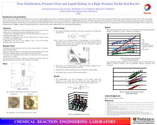
2. 2 Drilling Engineers must be able to predict circulating pressures in order to optimize hole cleaning, maximum the efficiency of the cuttings removal from below the bit. In a properly designed hydraulics program, around one half of the total circulating pressure drop should be through the bit. Many people refer to the pressure drop through the bit as the friction loss through the bit. In reality friction is such a small part of the pressure drop through the bit, that it can be ignored. Almost all the pressure drop through the bit is due to acceleration of the mud through the jets.Drilling Engineers must be able to predict circulating pressures in order to optimize hole cleaning, maximum the efficiency of the cuttings removal from below the bit. In a properly designed hydraulics program, around one half of the total circulating pressure drop should be through the bit. Many people refer to the pressure drop through the bit as the friction loss through the bit. In reality friction is such a small part of the pressure drop through the bit, that it can be ignored. Almost all the pressure drop through the bit is due to acceleration of the mud through the jets.
3. 3 1.7-3 For multiple nozzles in parallel Vn is the same for each nozzle even if the dn varies!
This follows since Dp is the same across each nozzle. Since the fluid velocity through all the nozzles is equal, the pressure drop through each nozzle is equal. The nozzle velocity can be calculated with the two above equations. If we set the two equations equal, we can solve for the pressure drop across the bit. In drilling we normally assume a nozzle discharge coefficient of 0.95.Since the fluid velocity through all the nozzles is equal, the pressure drop through each nozzle is equal. The nozzle velocity can be calculated with the two above equations. If we set the two equations equal, we can solve for the pressure drop across the bit. In drilling we normally assume a nozzle discharge coefficient of 0.95.
4. 4 1.7-4 Hydraulic Horsepower � of pump putting out 400 gpm at 3,000 psi = ?
Power, in field units: In order to optimize jet bit hydraulics we can either maximize the Hydraulic Horsepower at the bit or maximize the jet impact force. HHP is calculated above.In order to optimize jet bit hydraulics we can either maximize the Hydraulic Horsepower at the bit or maximize the jet impact force. HHP is calculated above.
5. 5 1.7-5 What is Hydraulic Impact Force � developed by bit?
If: Jet Impact Force is calculated here.Jet Impact Force is calculated here.
6. 6 1.7-6 Laminar Flow Rheological Models
Newtonian
Bingham Plastic
Power-Law (ADE & API)
Rotational Viscometer
Laminar Flow in Wellbore
Fluid Flow in Pipes
Fluid Flow in Annuli To calculate the frictional pressure in the annulus and the drill string, we must first determine which fluid model to use. The simplest are the Newtonian model and the Bingham Plastic model. We determine the rheological properties with a rotational viscometer. We also must determine if the flow regime is laminar or turbulent.To calculate the frictional pressure in the annulus and the drill string, we must first determine which fluid model to use. The simplest are the Newtonian model and the Bingham Plastic model. We determine the rheological properties with a rotational viscometer. We also must determine if the flow regime is laminar or turbulent.
7. 7 1.7-7 If we set two plates a known distance apart, L, and fill the space between them wit fluid, a force can be applied to one of the plates to set it in motion at a constant velocity. The moving plate will impart a shear force to the fluid. The shear force is equal to the force divided by the area of the plate. Once steady state has been reached, we will have a velocity profile in the fluid as shown in the lower right figure. The shear rate is equal to the velocity divided by the distance between the two plates, and is proportional to the shear rate. The proportionality constant is the viscosity.If we set two plates a known distance apart, L, and fill the space between them wit fluid, a force can be applied to one of the plates to set it in motion at a constant velocity. The moving plate will impart a shear force to the fluid. The shear force is equal to the force divided by the area of the plate. Once steady state has been reached, we will have a velocity profile in the fluid as shown in the lower right figure. The shear rate is equal to the velocity divided by the distance between the two plates, and is proportional to the shear rate. The proportionality constant is the viscosity.
8. 8 1.7-8 Newtonian Fluid Model In a Newtonian fluid the shear stress is directly proportional to the shear rate (in laminar flow):
i.e.,
The constant of proportionality, is the viscosity of the fluid and is independent of shear rate.
9. 9 1.7-9 Newtonian Fluid Model Viscosity may be expressed in poise or centipoise.
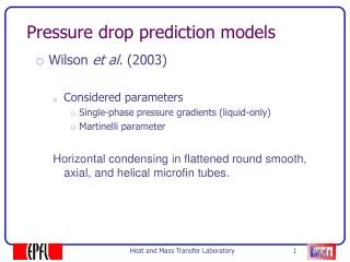
10. 10 1.7-10 Shear Stress vs. Shear Rate for a Newtonian Fluid If we plot shear stress vs. shear rate for a Newtonian fluid, we get a straight line passing through the origin. The slope of the line is the viscosity.If we plot shear stress vs. shear rate for a Newtonian fluid, we get a straight line passing through the origin. The slope of the line is the viscosity.
11. 11 1.7-11 Typical Drilling Fluid Vs. Newtonian, Bingham and Power Law Fluids This plot shows a plot of shear stress vs. shear rate for Newtonian fluids, power law fluids, and Bingham plastic fluids. The vast majority of our drilling muds, do not exhibit pure Newtonian, power law, or Bingham plastic behavior. It is more like the dashed line. So which one do we use? The one that fits best, usually Power Law, which will be discussed in lesson 14.1. We will discuss the latest version of the model. We call it the API Power Law Model.This plot shows a plot of shear stress vs. shear rate for Newtonian fluids, power law fluids, and Bingham plastic fluids. The vast majority of our drilling muds, do not exhibit pure Newtonian, power law, or Bingham plastic behavior. It is more like the dashed line. So which one do we use? The one that fits best, usually Power Law, which will be discussed in lesson 14.1. We will discuss the latest version of the model. We call it the API Power Law Model.
12. 12 1.7-12 Rheological Models 1. Newtonian Fluid:
2. Bingham Plastic Fluid: For a Bingham plastic fluid, the shear stress is proportional to the shear rate also, but the plot of the shear stress vs. shear rate does not pass through the origin, it intersects the vertical axis at some value greater than zero. The intersection is the yield point. The slope of the plot is the plastic viscosityFor a Bingham plastic fluid, the shear stress is proportional to the shear rate also, but the plot of the shear stress vs. shear rate does not pass through the origin, it intersects the vertical axis at some value greater than zero. The intersection is the yield point. The slope of the plot is the plastic viscosity
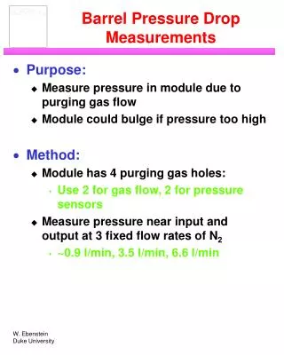
13. 13 1.7-13 RotatingSleeveViscometer This is a rotational viscometer which we use to measure the rheological properties of drilling fluids.This is a rotational viscometer which we use to measure the rheological properties of drilling fluids.
14. 14 1.7-14 Figure 3.6 This is a schematic of the rotating sleeve which rotates around a bob. The rotor and bob simulate the two parallel plates from earlier in the lesson. The rotor and bob are submerged to a scribe line in a mud sample. When the rotor is turned, it imparts a shear force to the mud, which in turn imparts a shear force to the bob. The bob is mounted on a torsion spring. The deflection of the spring can be seen by the deflection of a dial.This is a schematic of the rotating sleeve which rotates around a bob. The rotor and bob simulate the two parallel plates from earlier in the lesson. The rotor and bob are submerged to a scribe line in a mud sample. When the rotor is turned, it imparts a shear force to the mud, which in turn imparts a shear force to the bob. The bob is mounted on a torsion spring. The deflection of the spring can be seen by the deflection of a dial.
15. 15 1.7-15 Rheometer (Rotational Viscometer) Shear Stress = f (Dial Reading)
Shear Rate = f (Sleeve RPM)
Shear Stress = f (Shear Rate) Another representation of the rotational viscometer is shown above.Another representation of the rotational viscometer is shown above.
16. 16 1.7-16 Example A rotational viscometer containing a Bingham plastic fluid gives a dial reading of 12 at a rotor speed of 300 RPM and a dial reading of 20 at a rotor speed of 600 RPM
Compute plastic viscosity and yield point The size of the rotor and bob and the dial is calibrated so that the dial reading at 600 rpm minus the dial reading at 300 rpm is equal to the plastic viscosity. Also the dial reading at 300 rpm is equal to the Newtonian viscosity for a Newtonian fluid.The size of the rotor and bob and the dial is calibrated so that the dial reading at 600 rpm minus the dial reading at 300 rpm is equal to the plastic viscosity. Also the dial reading at 300 rpm is equal to the Newtonian viscosity for a Newtonian fluid.
17. 17 1.7-17 Example Since the shear rate at 300 rpm is exactly half of the shear rate at 600 rpm, if we plot these two dial readings vs. the rotational speed, we can draw a straight line through these two points. The intersection of this line with the vertical axis is the yield point, and can be calculated by subtracting the PV from the 300 rpm reading.Since the shear rate at 300 rpm is exactly half of the shear rate at 600 rpm, if we plot these two dial readings vs. the rotational speed, we can draw a straight line through these two points. The intersection of this line with the vertical axis is the yield point, and can be calculated by subtracting the PV from the 300 rpm reading.
18. 18 1.7-18 Gel Strength This yield point is really a bogus number. In actuality, if we measure the shear stress an very low shear rates, they do not plot on the straight line between the 600 and 300 rpm readings. It intersects the vertical axis at a somewhat lower value than the yield point. This intersection is referred to as the gel strength.This yield point is really a bogus number. In actuality, if we measure the shear stress an very low shear rates, they do not plot on the straight line between the 600 and 300 rpm readings. It intersects the vertical axis at a somewhat lower value than the yield point. This intersection is referred to as the gel strength.
19. 19 1.7-19 Gel Strength The yield strength, extrapolated from the 300 and 600 RPM readings is not a good representation of the gel strength of the fluid
Gel strength may be measured by turning the rotor at a low speed and noting the dial reading at which the gel structure is broken
(usually at 3 RPM)
20. 20 1.7-20 Gel Strength In field units,
21. 21 1.7-21 Velocity Profiles(laminar flow) This shows the velocity profiles inside pipe and in an annulus in laminar flow. The profile is bullet shaped with the maximum velocity near the center, and minimum velocities at the edges. The velocity at the edge is essentially the same as the walls of the pipe, or zero.This shows the velocity profiles inside pipe and in an annulus in laminar flow. The profile is bullet shaped with the maximum velocity near the center, and minimum velocities at the edges. The velocity at the edge is essentially the same as the walls of the pipe, or zero.
22. 22 1.7-22
23. 23 1.7-23 Table 4.3 - Summary of Equations for Rotational Viscometer Newtonian Model Here we have a summHere we have a summ
24. 24 1.7-24 Table 4.3 - Summary of Equations for Rotational Viscometer
25. 25 1.7-25 Total Pump Pressure Pressure loss in surf. equipment
Pressure loss in drill pipe
Pressure loss in drill collars
Pressure drop across the bit nozzles
Pressure loss in the annulus between the drill collars and the hole wall
Pressure loss in the annulus between the drill pipe and the hole wall
Hydrostatic pressure difference (r varies) The pump pressure is a function of all the above.The pump pressure is a function of all the above.
26. 26 1.7-26 Pressure losses for laminar flow.
27. 27 1.7-27 Types of flow To calculate pressure losses we must first determine if the flow is laminar (top) or turbulent (bottom right).To calculate pressure losses we must first determine if the flow is laminar (top) or turbulent (bottom right).
28. 28 1.7-28 Turbulent Flow - Newtonian Fluid We often assume that fluid flow is
turbulent if Nre > 2100 We commonly calculate the Reynolds number, and assume if (for a Newtonian fluid) the Reynolds number is greater that 2100, we have turbulent flow.We commonly calculate the Reynolds number, and assume if (for a Newtonian fluid) the Reynolds number is greater that 2100, we have turbulent flow.
29. 29 Turbulent Flow - Newtonian Fluid Pressure losses for turbulent flow for Newtonian and Bingham plastic fluids can be calculated with the above equations.Pressure losses for turbulent flow for Newtonian and Bingham plastic fluids can be calculated with the above equations.