Download
1 / 12
390 likes | 1.24k Vues
Tray Capacity, Pressure Drop, and Mass Transfer. When trays are designed properly, a stable operation is achieved wherein (1)vapor flow only through the perforations or open regions of the tray between the downcomers, (2)liquid flows from tray to tray only by means of the downcomers ,

E N D
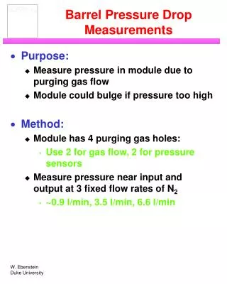
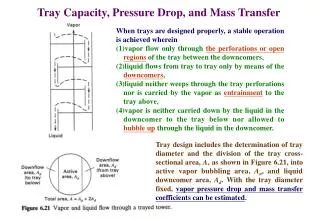
Tray Capacity, Pressure Drop, and Mass Transfer When trays are designed properly, a stable operation is achieved wherein (1)vapor flow only through the perforations or open regions of the tray between the downcomers, (2)liquid flows from tray to tray only by means of the downcomers, (3)liquid neither weeps through the tray perforations nor is carried by the vapor as entrainment to the tray above, (4)vapor is neither carried down by the liquid in the downcomer to the tray below nor allowed to bubble up through the liquid in the downcomer. Tray design includes the determination of tray diameter and the division of the tray cross-sectional area, A, as shown in Figure 6.21, into active vapor bubbling area, Aa, and liquid downcomer area, Ad. With the tray diameter fixed, vapor pressure drop and mass transfer coefficients can be estimated.
Tray Diameter ~For a given liquid flow rate, as shown in Figure 6.22 for a sieve-tray column, a maximum vapor flow rate exists beyond which incipient column flooding occurs because of backup of liquid in the downcomer. ~This condition, if sustained, leads to carryout of liquid with the overhead vapor leaving the column. ~Downcomer flooding takes place when liquid backup is caused by downcomers of inadequate cross- sectional area, Ad, to carry the liquid flow, but rarely occurs if downcomer cross-sectional area is at least 10% of total column cross-sectional area and if tray spacing is at least 24 in. ~The usual design limit is entrainment flooding, which is caused by excessive of carry-up of liquid, at the rate e, by vapor entrainment to the tray above. ~At incipient flooding, (e+L) L and downcomer cross- sectional area is inadequate for the excessive liquid load (e+L).
buoyant force gravitational force drag force entrainment velocity drag coefficient C=capacity parameter of Sounders and Brown ~Parameter C can be calculated from the above equation if the droplet diameter dp is known. ~In practice, however, C is treated as an empirical parameter using experimental data obtained from operating equipment. Sounders and Brown considered all the important variables that could influence the value of C and obtained a correlation for commercial size columns with bubble-cap trays. ~The value of C increases with increasing surface tension, which increases dp. Also, C increases with increasing tray spacing, since this allowed more time for agglomeration to a larger dp.
Using additional commercial operating data, Fair produced the more general correlation of Figure 6.24, which is applicable to columns with bubble-cap and sieve trays. FST=surface tension factor=(/20)0.2 FF=foaming factor FHA=1.0 for Ah/Aa0.10 and 5(Ah/Aa)+0.5 for 0.06 Ah/Aa0.1 =liquid surface tension, dyne/cm ~For nonfoaming systems, FF=1.0; for many absorbers, FFmay be 0.75 or even less. ~The quantity Ah is the area open to the vapor as it penetrates into the liquid on a tray. It is the total cap slot area for bubble-cap trays and the perforated area for the sieve trays. Fair utilizes a net vapor flow area equal to the total inside column cross-sectional area minus the area blocked off by the downcomer, that is, A-Ad.
~Figure 6.24 appears to be conservative for valve trays. This is shown in Figure 6.25, where entrainment flooding data of FRI, for a 4-ft-diameter column equipped with Glitsch type A-1 and V-1 valve trays on 24-in. spacing are compared to the correlation in Figure 6.24. ~For valve trays, the slot area Ah is taken as the full valve opening through which vapor enters the frothy liquid on the tray at a 90 angle with the axis of the column. ~Column diameter is calculated at both the top and bottom of the column, with the larger of the two diameter used for the entire column. ~Because of the need for internal access to columns with trays, a packed column is generally used if the calculated diameter is less than 2 ft.
Example 6.5 Estimate the required tray diameter for the absorber of Example 6.1, assuming a tray spacing of 24 in. a foaming factor of FF=0.90, a fraction flooding of f=0.80, and a surface tension of =70 dynes/cm. Example 6.6 Estimate the tray vapor pressure drop for the absorber of Example 6.1, assuming use of sieve trays with a tray diameter of 1 m, a weir height of 2 in., and a hole diameter of 3/16 in. Example 6.7 Estimate the Murphree vapor-point efficiency for the absorber of Example 6.1, using results from Example 6.5 and 6.6, for the tray of Example 6.6. In addition, determine the controlling resistance to mass transfer. Example 6.8 Using data from Example 6.5, 6.6, and 6.7, estimate the entrainment rate, the froth height in the downcomer, and whether weeping occurs.
Tray Vapor Pressure Drop Pressure drop (head loss) for a sieve tray is due to friction for vapor flow through the tray perforations, holdup of the liquid on the tray, and a loss due to surface tension: total pressure drop/tray, in. of liquid uo=hole velocity (ft/s) Co depends on the percent hole area and the ratio of tray thickness to hole diameter. For a typical 0.078-in.-thick tray with 3/16-in.-diameter holes and a percent hole area (based on the cross-sectional area of the tower) of 10%, Co may be taken as 0.73. Otherwise, Co lies between about 0.65 and 0.85. dry tray pressure drop, in. of liquid hw=weir height, in. e=effective relative froth density (height of clear liquid/froth height) =exp(-4.257Ks0.91) Ks=capacity parameter, ft/s=Ua(V/L-V)1/2 Ua=superficial vapor velocity based on active bubbling area, Aa=(A-2Ad), of the tray, ft/s Lw=weir length, in. For Ad/A=0.1, Lw=73% of the tower diameter qL=liquid flow rate across tray, gal/min C=0.362+0.317exp(-3.5hw) equivalent head of clear liquid on tray, in. of liquid except for tray perforation much smaller than 3/16-in. in diameter, DB(max), the maximum bubble size, may be taken as the perforation diameter, DH. pressure drop due to surface tension, in. of liquid
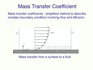
Mass Transfer Coefficients and Transfer Units is the interfacial area per unit volume of equivalent clear liquid is the average residence time of the gas in the froth is the average residence time of the liquid in the froth DV, DL=diffusion coefficient, cm2/s hl=clear liquid height, cm f=Ua/Uf, fractional approach to flooding F=F-factor=UaG0.5, (kg/m3)0.5/s
~At gas rates corresponding to a fractional approach to flooding of greater than 0.60, the mass transfer factor decreases with increasing value of f. This may be due to entrainment. ~On an entrainment-free basis, the curve in Figure 6.26 might be expected to at least remain at its peak value for conditions above f=0.6. depends strongly on F but is almost independent of liquid flow rate and weir height.
Weeping, Entrainment, and Downcomer Backup For a tray to operate at high efficiency, (1)weeping of liquid through the tray perforations must be small compared to flow over the outlet weir and into the downcomer, (2)Entrainment of liquid by the gas must not be excessive, and (3)Froth height in the downcomer must not approach tray spacing. Note: Weeping is associated with the lower limit of gas velocity, while entrainment flooding is associated with the upper limit. Weeping occurs at low vapor velocities and/or high liquid rates when the clear liquid height on the tray exceeds the sum of the dry (no liquid flow) tray pressure drop, due to vapor flow, and the surface tension effect. Thus, to prevent weeping, it is necessary that everywhere on the active area of the tray. If weeping occurs uniformly over the tray active area or mainly near the downcomer, a ratio of weep rate to downcomer liquid rate as high as 0.1 may not cause unacceptable decrease in the tray efficiency. Methods for estimating weep rates are discussed by Kister.
The prediction of fractional liquid entrainment by the vapor, defined as =e/(L+e), can be made by the correlation of Fair, given in Figure 6.28. ~As shown, entrainment becomes excessive at high values of fraction of flooding, f=Ua/Uf, particularly for small values of the kinetic energy ratio, FLV. ~The effect of entrainment on the Murphree vapor efficiency can be estimated by the following relation derived by Colburn, where EMV is the usual “dry” efficiency and EMV, wet is the “wet” efficiency: ~Equation (*) assumes that =KV/L=1 and that the liquid is well mixed on the tray such that the composition of the entrained liquid is that of the liquid flowing to the tray below. ~For a given value of the entrainment ratio,, the larger the value of EMV, the greater is the effect of entrainment. If weeping occurs only in the vicinity of the downcomer, no decrease in the value of EMV is oberved.
~The height of clear liquid in the downcomer, hdc, is always greater than the height of clear liquid on the tray because the pressure difference across the froth in the downcomer is equal to the total pressure drop across the tray from which liquid enters the downcomer, plus the height of clear liquid on the tray below to which the liquid flows, and plus the head loss for liquid flow under the downcomer apron. Thus, the clear liquid head in the downcomer is qL is the liquid flow in gpm and Ada is the area in ft2 for liquid flow under the downcomer apron. If the height of the opening under the apron, (typically 0.5 in. less than hw) is ha, then Ada=Lwha. The height of the froth in the downcomer is df is the froth density taken as 0.5.