Download

1 / 60
770 likes | 2.55k Vues
Plate Heat Exchanger Types and Maintenance Craft Master Brewers Association. Presented by: Mark Muncy – Alfa Laval Inc., Louisville, KY October 18, 2007. Discussion Outline. Basic Heat Transfer Compact solutions for Liquid/Liquid applications Gasketed plate

E N D
Plate Heat Exchanger Types and MaintenanceCraft Master Brewers Association Presented by: Mark Muncy – Alfa Laval Inc., Louisville, KY October 18, 2007 © Alfa Laval 2001
Discussion Outline • Basic Heat Transfer • Compact solutions for Liquid/Liquid applications • Gasketed plate • Semi-Welded plate heat exchanger • Welded plate heat exchanger • Compabloc • Spiral heat exchanger • Compact solutions for Two-Phase applications (evaporation and condensing) • Maintenance of compact heat exchangers • Questions © Alfa Laval 2001
Data needed to design any heat exchanger • Flows and temperatures for both sides • Fluid properties including: density, specific heat, thermal conductivity, and viscosity for at least two points. • For condensers and evaporators, data such as a condensing curve, boiling point elevation, and/or other parameters may be required. • Process conditions and limitations such as system pressure, potential for fouling or plugging, pressure drop limitations etc. • The supplier may be able to use their experience to assist in determining proper values from above. © Alfa Laval 2001
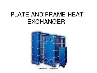
Types of Heat Exchangers • Shell and Tube (Most common in industry) • Gasketed plate and frame • Welded plate and frame • Spiral heat exchanger • Plate coils • Tubular heat exchanger • Scraped surface heat exchanger © Alfa Laval 2001
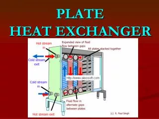
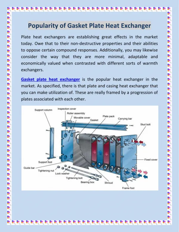
The Plate Heat Exchanger © Alfa Laval 2001
Corrugated Plate Technology AdvantagesMechanical StrengthContact PointsSurface EnhancementCreate Turbulence © Alfa Laval 2001
Heat Transfer Formula #1 Q = mCp(T – T ) HI HO • Where • Q = heat transferred (BTU/hr) • m = mass flow rate (hot fluid) (lb/hr) • C = specific heat (hot fluid) (Btu/lb,F) • T = hot fluid entering temperature (F) • T = hot fluid leaving temperature (F) p HI HO © Alfa Laval 2001
Heat Transfer Formula #2 Q = U A (LMTD) • Where • Q = heat transferred • U = overall heat transfer coefficient • A = heat transfer surface area • LMTD = log mean temperature difference © Alfa Laval 2001 05 1/99
Therefore m C (T - T ) U (LMTD) A = HO HI P Determining Heat Transfer Area mCp(T – T ) =U A (LMTD) HI HO Determining Proper “U” value is the key!! © Alfa Laval 2001
Tube Plate Spiral Items That Effect “U” value and Fouling Tendency • Channel Geometry (turbulence) • Fluid velocity and wall shear • Fluid Properties (particularly viscosity) • *Viscosity also has a major impact on the pressure drop that will be seen in the heat exchanger © Alfa Laval 2001
Why Use a Compact Heat Transfer Solution? • Lower Capital Cost • Better heat recovery = Energy Savings! • Can be expanded (PHE) for future upgrades • Less weight and smaller footprint • Low hold up volume means quicker system response time. • Can be easily chemically or mechanically cleaned © Alfa Laval 2001
PHE Advantages PHE S&T ------------------------------------------------------------------------------------------ Total Weight, drained, tons 16 96 Total Weight, operating, tons 19 136 Floor area, installation, ft2 150 1130 Floor area installation & maintenance, ft2 225 2045 Heat load per unit, million BTU/hr 45 30 Number of units 4 6 © Alfa Laval 2001
T HI T CO T HO T CI Countercurrent Flow Temperature Length of Channel
T HI T HO T CO T CI Cocurrent Flow Temperature Length of Channel
Plate Heat Exchanger Advantage True “Countercurrent” Flow Means a Very Close Temperature Approach Possible! Very close temperature approach (Within 3-5oF) In T1 Out Temperature cross T1 T2 Out In T2 Cont… © Alfa Laval 2001
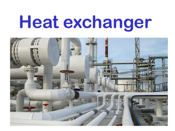
PHE uses in the World Today • Central cooling engineering • Food and dairy industries • Heating, ventilation and air conditioning • Oil and gas production and refining • Petroleum and chemical process industries • Pulp and paper industries • Hydrocarbon processing industries • Light industries • Metal recovery industries • Refrigeration and air conditioning • Steel and metal works • Sugar, distillery and fermentation
Single Pass, Parallel Flow 1 x 5 Pass/Channel: Hot Side Cold Side 1 x 4 Hot Out Cold In Cold Out Hot In © Alfa Laval 2001
Multi-Pass, Parallel Flow 2 x 4 Pass/Channel: Hot Side Cold Side 1 x 4 + 1 x 5 Cold Out Cold In Hot In Hot Out © Alfa Laval 2001
Wide-Gap Plate Heat Exchanger Free Flow Channels for Fibrous or Particle Laden Fluids Such as Mash, Beer or Stillage. Non-Clogging Port Design Prevents Build-up of Solids in Entrance Area © Alfa Laval 2001
Double Sided Wide Gap Heat Exchanger Single Side Wide Gap Heat Exchanger © Alfa Laval 2001
600 500 400 300 200 100 5° 0 100 200 300 400 500 600 700 Performance Improvements bytype of sealing system All-Welded PHE Semi-Welded PHE Design Pressure (psi) Gasketed PHE Temp (°F)
Semi-Welded Plate Exchanger • Aggressive Media On One Side • High Heat Transfer Efficiency • Flexible For Cleaning And Expansion © Alfa Laval 2001
Semi-Welded Plate Heat Exchanger Welded channel for aggressive fluid Gasketed channel for non-aggressive medium Peripheral weld 38 1/99
Two-Phase Applications for Compact Heat Exchangers • 190/200 Proof Condenser • Distillation Column Reflux and Vent Condensers • Distillation Column Reboilers • Evaporator Station Final Condenser • Regen Condenser • Ammonia Vaporizer • Many other applications in various industries © Alfa Laval 2001
An Innovation for Vacuum Condensing • Innovative hole configuration • Innovative pattern for condensation • Asymmetric channels • Semi-welded technology © Alfa Laval 2001
AlfaCond in evaporation systems © Alfa Laval 2001
AlfaCond in distillation systems © Alfa Laval 2001
Honeycomb Pattern • The plate edges of some newly designed plates are corrugated in such a manner that they form a honeycomb pattern. This provides mechanical support and a visual aid that the plates have been correctly hung in the frame.
Honeycomb Pattern • Improperly hung plates, or those which do not alternate A,B,A,B….. will disrupt the honeycomb pattern.
Gaskets…….Purpose • Gaskets are the sealing strips which are fastened to each plate. They mate up against the back side of the adjacent plate, forming a sealed flow channel.
Operating Parameters Which DirectlyAffect The Service Life Of A Gasket • Working Pressure- the higher the working pressure, the shorter the service life. • Difference In Pressure- the greater the differential pressure, the shorter the service life. • Fluid Temperature- The higher the gasket temperature, the shorter the service life. • Aggressive Fluids
Other Factors Affecting Gasket Life • Exposure to Ultra-Violet Rays • Ozone - electric motors, welding
Gasket…….Material • Gaskets can be made of rubber, fiber, or plastic. Gasket selection is based on the specific application or duty of the heat exchanger. • Majority of gasket material is rubber.
Gasket……Temperature Ratings • Nitrile (NBR)…………….230 degrees F • EPDM……………………320 degrees F • Viton…………..…………350 degrees F
Gasket……Types • Glue-On • Clip-on
Opening Your Heat Exchanger • Dismantle any piping connected to the pressure plate.
Opening Your Heat Exchanger • Inspect the sliding surface of the carrying bar, and the pressure plate roller.
Opening Your Heat Exchanger • Mark the plate assembly on the outside by a diagonal line, or number the plates in sequence. Then measure and note the “A” dimension.
Remaining bolts with wearing washer • When closing these are tightened last • When opening these are removed first Frame – 6” and larger • Tightening bolts to allow easy opening • Four tightening bolts have bearing boxes • These are used for opening and closing the unit
Opening Your Heat Exchanger • Pattern for removal of the tightening bolts on a model M10. First remove the two center bolts so that only the four outside corners remain.
Closing Your Heat Exchanger • Closing your heat exchanger to the proper “A” dimension is critical to leak free operation.
Troubleshooting • Identifying The Problem(s) Leakage Heat Transfer Performance High Pressure Losses
Leakage • Internal Leakage: When internal leakage occurs, 99.9% of the time there is a crack or pin holes in the plate(s). Fix: Dye Pen Test All Plates, Replace Bad. Exception To The Rule: Check Plate Alignment. Adjust Hangers. Check Leak Detect Area.
Leak Detection • Special venting ports are an integral part of the gasket design to prevent cross contamination.
Leakage • External Leakage: Locate the area of leakage. Is the leak constant or periodic? Is the unit subjected to extreme temperature shocking? Fix: Check The “A” Dimension. The “A” Dimension is the length of the plate pack in the heat exchanger that ensures proper gasket compression and contact between plates. Acceptable range is +/- 1%. Check Plate Alignment. You May Need To Regasket The Unit.