Download
1 / 11
110 likes | 482 Vues
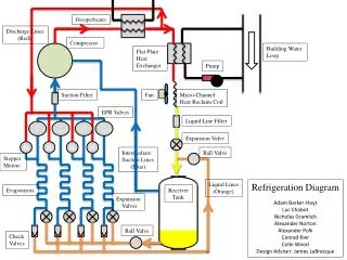
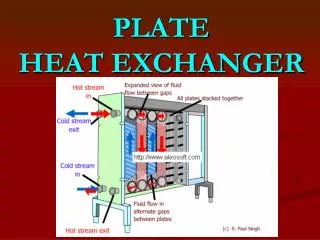
PLATE & FRAME HEAT EXCHANGER. By Farhan Ahmad Department of Chemical Engineering, University of Engineering & Technology Lahore. Design of PHE. LMTD Method ε- NTU Method. LMTD Method. For both looped and series flow arrangements. The steps involved in the method are given next.

E N D
PLATE & FRAME HEAT EXCHANGER By Farhan Ahmad Department of Chemical Engineering, University of Engineering & Technology Lahore engineering-resource.com
Design of PHE • LMTD Method • ε- NTU Method engineering-resource.com
LMTD Method • For both looped and series flow arrangements. • The steps involved in the method are given next. For series flow : 1 . Calculate the heat duty. Determine the inlet and outlet temperatures for both the fluids. 2. Estimate LMTD for counterflow arrangement. 3. Estimate Reynolds number for the each stream, assuming an exchanger containing one thermal plate, one pass for each stream, as given: where n is the number of substreams. For series flow, n = 1. 4. Estimate heat-transfer coefficient on both sides 5. Estimate overall heat-transfer coefficient taking into account the wall thermal resistance. 6. Estimate the total heat-transfer area from A = q/U LMTD. 7. Estimate the number of plates from, N=A/Ap where Ap is the area of a plate engineering-resource.com
LMTD Method For parallel flow or looped flow : 1-7. Repeat steps 1 to 7 already given. 8. From the number of thermal plates calculated in step 7, n, is determined for both the fluids. • For odd N, values of n, will be equal for both fluids, • whereas for even N, n, will be different for both the fluids, and one fluid will have an additional substream compared to the other. 9. The values of n, determined in step 8 are compared with the corresponding values assumed in step 3. If the calculated values do not agree with the assumed values, steps 3-9 are to be repeated, replacing the assumed values with the values calculated from step 8 until there is agreement between the two. engineering-resource.com
ε- NTU Method 1. Calculate the heat load, q, and from it determine the inlet and outlet temperatures for both the fluids. 2. Calculate the bulk mean temperature and determine the thermo physical fluid properties. Estimate the heat capacity rate ratio, C*. 3. Estimate the heat-transfer effectiveness, E, using the relation 4. Assume an exchanger containing an infinite number of channels and find the required NTU using the appropriate E-NTU relation. 5 . Estimate Reynolds number for the each stream, assuming an exchanger containing one thermal plate, and one pass for each stream. 6. Calculate the heat-transfer coefficient on both sides. Estimate the overall heat-transfer coefficient, taking into account the wall thermal resistance. engineering-resource.com
ε- NTU Method For series flow : 7. Estimate the approximate number of thermal plates using the equation where Δtm is the mean temperature difference. 8. Assuming an exchanger of N + 1 channels, determine NTU from the appropriate E-NTU relationship. 9. Recalculate N from Eq. 18. 10. Repeat calculations in steps 8 and 9 until the calculated value of N in step 9 matches the assumed value in step 8. engineering-resource.com
ε- NTU Method For parallel flow or looped flow • In a design involving looped flow patterns, the overall coefficient requires recalculation during each iteration because the channel flow rates become less with the addition of channels in parallel. The calculation procedure for looped flow is as follows: 7. Assuming an exchanger of N thermal plates, calculate the overall heat-transfer coefficient as in step 6. 8. Estimate the approximate number of thermal plates using Eq. 18. 9. Assuming an exchanger of N + 1 channels, determine NTU from the appropriate E-NTU relationship for looped flow. 10. Recalculate the overall heat-transfer coefficient as per step 6 and recalculate N with Eq. 11. Repeat calculations in steps 9 and 10 until the calculated value of N matches with the assumed value. engineering-resource.com
Heat Transfer Correlations • Effective plate width • Effective length of flow • Equivalent Diameter engineering-resource.com
Pressure drop Correlations • Friction factor • Comparison • Pressure drop in PHE • Expressions for pressure drop • Inlet or outlet ports • Associated with plate flow passage • Due to elevation changes • Specific pressure drop engineering-resource.com
Types of Plates Intermating troughs or washboards patterns chevron or herringbone pattern engineering-resource.com
High or Low Theta plates Chevron angle engineering-resource.com