Inverter Circuits
Inverter Circuits. Provide a variable voltage, variable frequency AC output from a DC input Very important class of circuits. Extensively used in variable speed AC motor drives for example (see H5CEDR)

Inverter Circuits
E N D
Presentation Transcript
Inverter Circuits • Provide a variable voltage, variable frequency AC output from a DC input • Very important class of circuits. Extensively used in variable speed AC motor drives for example (see H5CEDR) • We have already seen how the fully controlled thyristor converter can operate in the inverting mode ( > 90O) - however that is limited: • Can only invert into an existing AC supply • Voltages must already be present to provide natural commutation of thyristors • The circuits we will look at here are much more versatile and can provide an AC output into just about any kind of load • Three phase and single phase versions are possible - principles are the same
Q1 D1 E/2 IAC DC Supply (E) O X Don’t worry about where current goes yet E/2 D2 Q2 Basic Inverter Leg (1) • Basic building block is the “2-level inverter leg” • Capacitor does not have to be split - O provides a convenient place to reference voltages to for understanding • Obviously never gate Q1 and Q2 at the same time! - “shoot through” causes destruction • Normal mode is to use complementary gating for Q1 and Q2 • In practice a small delay must be introduced between turning Q1 off and Q2 on (and vice versa) to avoid “shoot through” due to finite switching times • We will ignore the effect of this and assume perfect switching
Basic Inverter Leg (2) • Output voltage depends on gated device only and not on current direction • Circuit produces 2 voltage levels • Equivalent circuit: • Not often used on its own - but provides basic building block for other circuits
IDC DC LINK D1 D3 E/2 Q1 Q3 IAC DC Supply (E) X O VAC load Y Q2 Q4 E/2 D2 D4 Single Phase Inverter H-bridge (1) • Uses 2 inverter legs • Energy flow in both directions possible - circuit can be used as a rectifier - see later
Single Phase Inverter H-bridge (2) • VXO, VYO are 2-level waveforms (E), VXY can be a 3-level waveform • Note: this is called a “2-level” circuit since each leg is a 2-level leg • Circuit can produce +E, 0 and -E in response to gating commands, regardless of current direction • We can synthesize (on average) any waveform we like by switching for varying amounts of time between +E, 0, -E • For example, for variable DC we could use: • Q1, Q4 gated 0 < t < dT, Q2, Q3 gated dT < t < T • Average (DC) output = Ed - E(1-d) = E(2d-1) • Used like this (or similarly) circuit is called a “Chopper” - see H5CEDR for application to DC motor drives
Single Phase Inverter H-bridge (3) • To get AC output, we could operate like described previously, but dynamically vary the duty cycle (d) to follow an AC demand • This is called Pulse-Width Modulation (PWM) - see lhandout for what the waveform looks like • For this to be effective, the switching frequency has to be an order of magnitude greater than the demand frequency • PWM produces an output waveform with a spectrum consisting of the wanted component + distortion components clustered (sidebands) around the switching frequency and its multiples
Single Phase Inverter H-bridge (4) • Some sort of filtering action is required to extract the desired component and eliminate the distortion • To produce an AC voltage we could use: • For an inductive load that requires a smooth current (eg an electrical machine), the machine inductance provides the filtering:
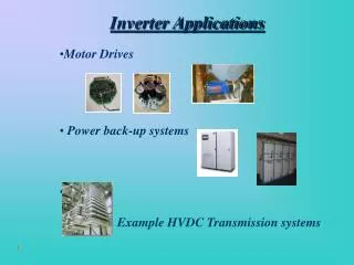
Inverter Application Examples • Single Phase • Three Phase
Single Phase Inverter Square wave operation • Return to PWM later - simplest method of voltage/frequency control is “quasi-squarewave” • Used to be very popular when power devices were slow and high switching frequencies were not possible • Gate each side of the bridge with a squarewave at the desired output frequency • Adjust phase shift between the two sides to get voltage control • See handout for waveforms • See handout on relationship between AC side and DC side harmonics
PWM Techniques • 2 Basic forms for single phase (H-bridge) inverter • 2-level PWM. • Each diagonal pair of switches is operated together. • Output is either +E or –E (hence name 2-level). • Gating pattern is Q1Q4 Q2Q3 Q1Q4. • 3-level PWM • All possible (allowable) gating patterns are used. • Output can be +E, 0 or –E. • Generation of PWM gating pattern. • Easiest method to understand is Natural Sampling (analogue method not often used now) • Most applications now use a microprocessor, microcontroller or DSP to generate the PWM pattern using a digital modulation technique.
Natural Sampling 1 • See handout for detail of comparison process • Definitions:
Natural Sampling 2 • Frequency ratio (FR) can be integer (synchronous PWM) or non-integer (asynchronous PWM). • It is normal now to keep the carrier frequency fixed as the modulating frequency is varied – hence most PWM today is asynchronous. • Modulation Index (MI) tells us how large the modulating frequency component at the inverter output will be for a given DC link voltage. • Modulation Depth (MD) tells us how much we have modulated the pulses by (compared to an unmodulated 50% duty cycle carrier frequency squarewave). • For Natural Sampling MI = MD (provided MD < 1) • Hence control of amplitude and frequency of the modulating wave, provides direct frequency and voltage control at the inverter output. • Spectrum of 2-level PWM: Modulating component + sidebands around carrier frequency + sidebands around 2 times carrier frequency etc – see Handout
Natural Sampling 3 • 3-level use the same carrier for both sides of the H-bridge, but invert the modulating wave (180O shift). • VXO and VYO are 2-level, VXY is 3-level. • Components clustered as sidebands around odd multiples of the carrier frequency are in-phase in VXO and VYO and therefore cancel in VXY • Other components are in anti-phase in VXO and VYO and therefore add in VXY • 3-level produces less distortion for given carrier (switching) frequency – see Handout
Digital PWM • Natural sampling is not suitable for a microprocessor implementation. • Switching instants occur at the natural intersection between a triangle wave and a sinewave. • Equation determining the switching instants has no analytical solution (transcendental equation) and can only be solved by iteration – no good for real time calculation. • Microprocessor implementation uses the Regular Sampling method (or something similar). • There are no continuous modulating or carrier waves. • Time is divided into a sequence of carrier periods of width TC. • The modulating wave exists as a series of samples, sampled either every TC (symmetric PWM) or every TC/2 (asymmetric PWM). • One pulse is produced within each carrier period. • Pulsewidth depends on either one sample of the modulating wave (symmetric PWM) or two samples of the modulating wave (asymmetric PWM).
Regular SamplingSymmetric PWM • Let SK-1, SK, SK+1 etc be the samples of the modulating wave sampled at rate (1/TC). • Assume the modulating wave is scaled so that its peak amplitude is unity. • Simple equations define the pulsewidths – OK for real time digital implementation. • MD MI for regular sampling
Regular Samplingasymmetric PWM • Let SAK-1, SBK-1, SAK, SBK, SAK+1, SBK+1 etc. be the samples of the modulating wave sampled at rate (2/TC). • Assume the modulating wave is scaled so that its peak amplitude is unity. • Asymmetric PWM produces less distortion than symmetric PWM for a given carrier (switching frequency) • MD MI as for symmetric sampling
PWM Miscellaneous • Choice of carrier frequency • Compromise depending on switching losses in the inverter and output waveform distortion. • Also depends on the switching device technology used. • Typical values: 16kHz (1kW), 5kHz (100kW), 1kHz (1MW) – assuming IGBT devices. • Other types of PWM (not a complete list) • Space Vector PWM • Similar to regular sampling, but derived from the “space-phasor” representation of 3-phase quantities. Popular in “Vector controlled” induction motor drives (see H54IMD) • “Optimised PWM” • Spectrum of PWM is defined mathematically in terms of the pulsewidths. Numerical techniques are then used to calculate the pulsewidths to meet a particular performance target. • For example: eliminate certain harmonics, minimise weighted sum of harmonics etc. • Not popular except in some special applications
DC LINK DC Supply (E) O A B C 3-phase load 3-phase Inverter • VAO etc are 2-level (±E/2), VAB etc are 3-level (±E and 0). • Each leg is modulated using the same carrier, but with modulating waves 120o apart (3-phase). • The large carrier frequency component in VAO etc cancels in VAB etc. • PWM control of inverter gives variable voltage and variable frequency output. • Average power flow can be bidirectional if the DC source can accept power input.
3-phase AC to AC(rectifier - inverter) RECTIFIER DC LINK INVERTER 3-PHASE SUPPLY 3-Phase AC Load • Industry “workhorse” - made from a few kW to MW - particularly for Induction Motor drives. • Unidirectional power flow since diode rectifier can't accept power reversal. • Energy can only be extracted from motor (braking) if some form of resistor is connected across the DC link during this mode. Common practice in industrial drives - known as dynamic braking. • AC supply current waveforms are poor because of diode rectifier.