Superconductivity UK
Superconductivity UK. Cables, SMES, Synchronous Condensers and grid stability. Dr. Philip Sargent, Diboride Conductors Ltd. R&D. Demonstration. Pre-commercial. Supported commercial. Commercial. Large-scale Innovation. Technology push. Market pull.

Superconductivity UK
E N D
Presentation Transcript
Superconductivity UK Cables, SMES, Synchronous Condensers and grid stability Dr. Philip Sargent, Diboride Conductors Ltd.
R&D Demonstration Pre-commercial Supportedcommercial Commercial Large-scale Innovation Technologypush Marketpull UK Innovation Systems for New and Renewable Energy Technologies, June 2003. ICCEPT
1967 Superconducting Cable >100 GW dc, >1000 km !
School H2 Home Supermarket Family Car Nuclear plant H2 DNA-to-order.com MgB2 SuperCity Vision National Climate Change Technology Initiative (NCCTI – “Necktie”) “Absolutely Zero GHG Emissions by 2050” George W. Bush P.M. Grant, The Industrial Physicist, Fall Issue, 2001
Cables Siemens NKT Denmark
Cable Projects • Long Island: 2004, 600m 138kV $30m • Benefit is 3x duct capacity (AMSC) • Albany/Hudson 450m $26m (Sumitomo/IGC/BOC) • Columbus 300m 2005 (Ultera/Southwire) • Tokyo 100m, 114 MVA (TEPCO/Sumitomo) • Detroit 120m 24 kV, 100 MVA warm dielectric (Pirelli, AMSC) – vacuum leak. • Copenhagen 100m 36kV, 1.8kA • Southwire 30m 12.4kV 1.25kA, 10,000 hours
Cable Losses • AC Losses (hysteresis) • I2R losses in joints • Dielectric losses • Thermal conduction losses (side) • Thermal conduction losses (terminations) • Pumping losses (friction of LN)
Cold or Warm Dielectric Higher thermal loss No stray field Low thermal loss Cheaper to make www.supercables.com
Coaxial or Trifoil www.supercables.com
RAND HTS cable study 2002 • Technical feasibility and tradeoffs only!
Pirelli HTS Cable Study 2002 • “The most attractive scenarios are those where the higher power transfer density can be exploited fully and cannot be obtained with conventional technology. In these cases congestions can be reduced and system reliability improved.” “Modifying cooling temperature with refrigeration, transfer capability can be increased 30-50%” Mansoldo, Jan.2002, PES-IEEE NY.
Cables Summary • Losses are roughly equal: thermal, AC hysteresis, dielectric • Primary benefits are for reusing scarce duct space in retrofit in inner cities (10s of km/y) • Long distance and new AC installations are infeasibly expensive due to LN cryogenics, not materials cost – 20x overhead line. • HV DC cables are another matter…
Conectus Roadmap 4K – 77K pre-commercial: R&D, prototypes, field-testsemerging marketmature market
ISIS 2002 $38b by 2020
SuperconductivityPower Markets (ISIS) 2003 DC Power $20b/y
Generators • 1970s GE 20MW NbTi in liquid helium • 1990s Japanese 70MW, also NbTi • 4K liquid helium cryogenics “difficult” • Economics attractive: size, efficiency • Same technology as motors, but BIG • Therefore, follow motor market. • GE/AEP/DOE 100MW project due 2005 (1.8MW generator tested 23 July 2003)
Generator Design • 1/2 length • 2/3 diameter • 98.6% efficient • cryogenics energy cost is only 2% of the total losses • 50 MW 3600rpm • (Jan.2002)
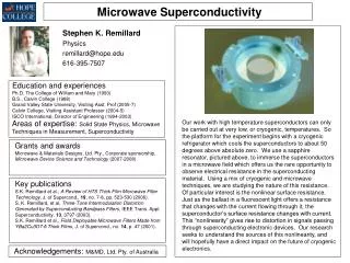
Synchronous Condenser Conventional stator HTS rotor 10 MVAR, 13.8 kV at 60 Hertz
Uses Motor Technology 5MW USNavy motor 36MW motor design
Benefits • Transient dynamic voltage stability (leading and lagging VARs) • Voltage support and stability improvement • HTS rotor increases the over-excitation and under-excitation output limits to its full-rating without loss of critical clearing time following a transient fault. Increases capacity: reduces losses • Power factor correction in steady state operation • Stable operation in leading or lagging mode • Less rotor maintenance: no thermal fatigue so used for peaking as well as base load • Minimizes operating power • Minimizes harmonic content
Delivered to TVA 8 days ago • 19 Nov. 2003 AMSC “SuperVAR” delivered at the Hoeganaes steel mill in Gallatin, Tennessee. • Compensates for the reactive power drawn by the steel mill’s arc furnace • North American Electricity Reliability Council (NERC) cited the need to ensure appropriate levels of reactive power as the highest priority.
Liquid Neon motors • AMSC 3.7MW • Siemens motor
Cryogenics • Liquid neon for 24-27K operation: useful for high field BSCCO. • A synchronous machine has effectively a “DC rotor”, • So AC losses are small in the rotor , • So gaseous helium has adequate heat transfer capability at 35 – 40K. • A superconducting stator is not imagined by BSCCO manufacturers, but may be OK with Magnesium Diboride.
Flywheel Energy Systems • Superconducting bearings increase the useful storage time from minutes to an hour or so. • Good for power quality control or transmission support, not load-levelling or peak shaving • Not as high a power rating as SMES, but more energy storage • Pirouette/BNFL in the UK, Boeing in USA
AMSC’s SMES • 3 MW instantaneous real power from the superconductor magnet NbTi/He • 8 MVAR of reactive power from the IGBT inverters.
SMES for stability • 115kV Northern Wisconsin to fix a network instability problem
Fault Current Limiters • FCLs have many applications • Save capital costs on other equipment • Many different designs (resistive, inductive) Mårten Sjöström and Diego Politano, ASC 2000
ORNL Model June 2003 Assumed market growth rates Motors >370kW
Efficiencies • Transformers are attractive because of their efficiency and safety (no oil). • Generators are attractive because of their efficiency. • But much higher value is gained by reducing capital expenditure by using Synchronous Condensers, Dynamic SMES and Fault Current Limiters. • Therefore, efficiency in these new devices is not a prime concern.