Download
1 / 43
450 likes | 1.54k Vues
Modeling Software Architecture with UML + CPN Jianli Xu Nokia Research Center Joint Tutorial of CPN’04 & MOCA’04 Aarhus 11.10.2004 Outline of the talk An example of describing software architecture with UML Experience and lesson learned in modeling architecture with UML

E N D
Modeling Software Architecture with UML + CPN Jianli Xu Nokia Research Center Joint Tutorial of CPN’04 & MOCA’04 Aarhus 11.10.2004
Outline of the talk • An example of describing software architecture with UML • Experience and lesson learned in modeling architecture with UML • Validating UML architecture models – the architectural profile centric approach • Create Architecture Behavioral Model Using UML + CPN
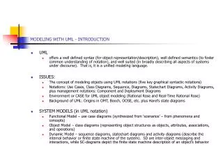
Some knowledge of UML and Software Architecture • UML (Unified/Universal Modeling Language) 1.4, 1.5 and 2.0 (?) • Class diagram, sequence diagram, collaboration diagram, statechart, and deployment diagram • Software Architecture • The fundamental organization of a system, embodied in its components, their relationships to each other and the environment, and the principles governing its design and evolution. - ANSI/IEEE Std 1471-2000, Recommended Practice for Architectural Description of Software-Intensive Systems • Hundreds of definitions on CMU web page: http://www.sei.cmu.edu/architecture/definitions.html • “In most of the successful software projects, the expert developers working on that project have a shared understanding of the system design. This shared understanding is called ‘architecture’. This understanding includes how the system is divided into components and how the components interact through interfaces. These components are usually composed of smaller components, but the architecture only includes the components and interfaces that are understood by all the developers” – Ralph Johnson
Problem Description • Problem Description • Our system, “Image recognition for X-ray”, is an application subsystem to be developed for Symbian / S60 platform based Smart Phone with a special attached camera.
Step 1. Create the system context model • System context model makes the developers to understand the implementation environment. • The context model defines the border / scope of your system • identifies the external actors (including external software systems, users, controlled hw, etc.) and the interfaces with them • defines the platforms (hardware and software), and standards that the system is built upon or confirmed to • The context model may have UML diagrams that show • The dependencies between the system and its environment, if possible, the interface at a certain detailed level; • The deployment of the system to hardware platform at sub-system or higher level.
Step 1. Create the system context model -cont. • The context model
Step 1. Create the system context model -cont. • The context model – with stereotypes to clarify different types of system elements
Step 2. Describe the Structure View • The system structure is described / designed with a structure view • The structure view shows the hierarchical decomposition of the system into subsystem (the top-level view) and components (in the sub-system structure view), and describes the logical relations among them in the corresponding top-level view or subsystem level views. • Class diagrams are used
Step 2. Describe the Structure View -cont. • Top level structure view
Step 2. Describe the Structure View -cont. • Subsystem structure view
Step 2. Describe the Structure View -cont. • Subsystem structure view
Step 3. Create the Behavior View -cont. • It is about how to model the system behavior • A behavior view describes the realization scenarios of the main use cases specified in the system requirements, unveils the internal behavior or activities of the system by describing the inter-component interactions as high-level interaction diagrams • Sequence and collaboration diagrams are usually used
Step 3. Create the Behavior View -cont. • Behavior view The sequence diagram shows a system level scenario of how to processing a X-ray picture
Step 3. Create the Behavior View -cont. • Component level realization scenarios in the behavior view
Step 4 … Create Other Architectural Views • What other views are needed depends on the major stakeholders and key system requirements, you may need, i.e. organization view, build view, security view, resource view, etc. • The component diagram shows a example of build view
Summary of the Example • UML notations used in structure view and other static views • UML notations used in behavior view • Sequence diagram, collaboration diagram, statechart (?)
Experience and Lessons Learned in Modeling Architecture with UML • General UML notations can not convey the necessary semantics for architecture elements in a particular application domain • Lack of pragmatic approach of specifying architectural rules and validating the architecture design • Behavior specification is too heavy • Too many sequence /collaboration diagrams are needed to cover all necessary component interactions • State diagrams seldom used • not suitable to describe inter-component behavior • Too many states • Inconsistency likely to be introduced not only between behavior views and static views, but also between different parts of behavior descriptions • System behavior validation ?
Outline of the talk • An example of describing software architecture with UML • Experience and lesson learned in modeling architecture with UML • Validating UML architecture models – the architectural profile centric approach • Create Architecture Behavioral Model Using CPN + CPN
Architectural Profile Centric Approach • Use UML profiles to define domain-specific architectural conventions, patterns, and construction rules → architectural profiles • Check whether a given architectural design conforms to a given profile → architecture validation • Automate the process, i.e., create suitable tools for the validation and maintenance process → tool support
UML Architecture Profiles • An UML profile is essentially defined by extending the specification of the UML metamodel using UML’s built-in extension mechanisms: stereotypes, constraints, and tagged values • An architectural profile is an UML profile that presents a set of architectural rules and specifies a subset of UML models that can be considered “legal” in a particular context • Architectural profiles can be specified in visual forms, or intuitive examples, of what kinds of structures the architectural style in question allows
UML Architecture Profiles – a simple example Stereotype definition Constraint definition
UML Architecture Profiles – a simple example • Interpretation of a architectural profile
UML Architecture Profiles – a real example • Stereotype definition part Constraint definition part
Validating the Architectural Model • Exercise: Using the architectural profile given in the previous slide to check the structural view in the first example, see how many violations you can find.
Outline of the talk • An example of describing software architecture with UML • Experience and lesson learned in modeling architecture with UML • Validating UML architecture models – the architectural profile centric approach • Create Architecture Behavioral Model Using UML + CPN
Create Architecture Behavioral Model Using CPN • Why CPN? • A classical approach: • UML structural model → CPN model • Extension to the classical approach: • UML structural model → CPN model → UML behavior model • A new approach: • UML behavior model → CPN model (complete?, integrated, consistent architectural behavior model)
Why Use CPN for Architecture Behavior Modeling • It is an executable Formal graphical language, both state and action oriented (compare to statechart) • The following characteristics are of special interest for modeling software architecture : • Compositional way of model building • Capability of modeling concurrency • Capability of modeling data flows (object definition and manipulation) • Time concept • Programmable and extensible • Good tool support (Design/CPN tools and the new CPN tool) make it possible to model industry systems • One of the most important criteria for industry to choose a formal approach • Positive experiences from many research and industry projects
From UML Structural Model to CPN behavior model • UML structural models have already specified components, their interfaces and component relationships via interface dependencies • Keep structure similarity between UML structural models and the CPN model • Mapping subsystem/component structure directly or naturally to the page structure of CPN model • Define the run-time correspondents of static concepts • Model the run-time components and data/state objects with CPN tokens • Flexible and reconfigurable • Model can scale up for systems having many types and/or instances of component • All other control and communication mechanisms that are unlikely to change are modeled with the net structure, i.e. the infrastructure platform (OS and middleware) in a product family
Case Study 1 – CPN Behavior Model of Mobile Phone Product Family
Case Study 1 – CPN Behavior Model of Mobile Phone Product Family • Support the specification of a large system • Reflect properly the execution time system structure allowing refutation and supporting development • Support a generic abstraction of the product family allowing to instantiate different products • Support simulation based on the use cases defined for the architecture • Allow quantitative measurements • Support analysis
Derive UML Behavior specification from CPN Model • Suppose a CPN model has been created following the classical approach, and the CPN model has captured the fundamental behavioral patterns and rules • UML sequence diagrams of correct component interactions can be generated from the CPN model • to create the system behavior specifications in the language of software developers • It is possible or worth to generate UML state or activity diagram from the CPN model?
Case Study 2 – CPN Model of UI Feature/Component Interaction for Mobile Phone UI Applications • The CPN model is created to specify correct feature interaction patterns based on the thorough study of • UI specification documents, • UI architecture design documents (with UML structural models) • Captures the basic concepts (components, communication, control) of the UI architecture from its UML structural model • Can be executed in the Design/CPN tools • The user can control the simulation through the animated phone on PC screen • Generates sequence diagrams from the simulation that show the flow events and messages between the software components • Generated sequence diagrams are used in the static documentation of the feature interaction patters
CPN model structure Model hierarchy • Applications (features) can be ”plugged” into the model • Provides real-time animation of the mobile phone UI during simulation Top level page
Input and Output of the CPN Model • Generates sequence diagrams from the simulation that show the flow events and messages between the software components
From UML Behavioral Model to CPN Model Question: Suppose we have a behavior view of an software architecture described with UML behavioral diagrams (sequence/collaboration diagram, state diagram, activity diagram), Can we formally validate this UML view with CPN? Partial solution: A set of UML sequence diagrams CPN model engine CPN behavior model automatically translated as initial markings about objects/components, events, messages, mandatory partial orders of events and messages
More Words about the Approach • Platform/product specific scheduling and communication mechanisms should be build in (similar to the previous two approaches) to rule out all “illegal” scenarios • The final model is used for analytical purpose, not for system behavior specification and simulation • Limits of formal methods (techniques and theory) • Number and size of scenarios are limited by the state space the CPN tools can handle • Once the engine and the necessary facilities created, UML behavior models can be formally analyzed by software architects/developers without seeing the CPN model
Case Study 3 – Analyze Resource Consumption Properties of Mobile Phone Applications • The analysis tools and their relationship • In the architecture models created in IBM/Rational Rose, sequence diagrams showing application interactions are instrumented with memory consumption properties of each object and main operation • The Rose UML sequence diagrams are translated automatically to data files that are then loaded into the CPN tool, and analyzed together with CPN model (engine) • Analysis results about possible memory consumption of the input scenarios are created by CPN tool as Excel files
CPN model engine • A generic CPN model is created to play the scenarios and generate the state space • Each execution corresponds to one particular interleaving of the individual events of the given scenarios. • The state space for the CPN model contains all possible interleaving. • An exhaustive traversal of the state space can find the worst-case memory usage, by finding a state which has a maximal value on the total Memory Usage place.
Usage of the model and tools • Where is the CPN model? Tool
Summary • UML can be used as an ADL, especially for describing the structural views of software architecture • Weak point of UML at modeling behavioral views of software architecture • CPN can be used as an alternative of UML behavior diagrams • CPN + UML • Approach to getting software architects/developers (non-CPN experts) to accept CPN
References • P. Selonen and J. Xu. Validating UML Models Against Architectural Profiles. in Proc. of 9th European Software Engineering Conf., pages 58–67, Helsinki, Finland, 2003. ACM. • J. Xu and J. Kuusela. Analyzing the Execution Architecture of Mobile Phone Software with Coloured Petri Nets. International Journal on Software Tools for Technology Transfer, 2(2):133–143, 1998. • L. Lorentsen, A.-P. Tuovinen, and J. Xu. Modelling of Features and Feature Interactions in Nokia Mobile Phones using Coloured Petri Nets. In Proc. of 23rd Petri Nets Conf., volume 2360 of LNCS, pages 294–313, Adelaide, Australia, 2002. Springer. • J. Jorgensen, S. Christensen, A.-P. Tuovinen, and J. Xu. Estimation of Memory Usage of Mobile Phone Software Using UML and Coloured Petri Nets. To be published at ISoLA 2004, Cyprus • CPN Tools. www.daimi.au.dk/CPNtools. • IBM Rational Rose. www-136.ibm.com/developerworks/rational/products/rose.