Download
1 / 12
140 likes | 876 Vues
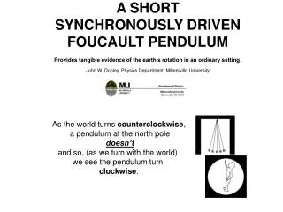
A SHORT SYNCHRONOUSLY DRIVEN FOUCAULT PENDULUM Provides tangible evidence of the earth’s rotation in an ordinary setting . John W. Dooley, Physics Department, Millersville University. As the world turns counterclockwise , a pendulum at the north pole doesn’t

E N D
A SHORT SYNCHRONOUSLY DRIVEN FOUCAULT PENDULUM Provides tangible evidence of the earth’s rotation in an ordinary setting. John W. Dooley, Physics Department, Millersville University As the world turns counterclockwise, a pendulum at the north pole doesn’t and so, (as we turn with the world) we see the pendulum turn, clockwise.
The earth rotates towards the east, causing the sun to “rise” in the east each morning. Viewed from above the north pole, the earth rotates with a counter-clockwise sense. The rate of rotation is once per day, so that the angular velocity is Imagine the earth as a frozen sphere of smooth ice. A person at location A slides a hockey puck due north, towards a person at location B. If the earth is not rotating the puck simply slides along a meridian (a great circle through the north pole) to B. If the earth rotates to the east then A has an eastward velocity of where l is the latitude of A. Now the result of the hockey puck experiment is different because A is traveling faster than B. The puck has the same eastward velocity component as point A. It crosses B’s path to the east of B, because B is moving slower. Since B is still due north of A, the direction of the puck’s trajectory has been rotated due to the rotation of the earth. The rate of change of direction of the puck’s velocity turns out to be The minus sign represents the fact that, if the earth is rotating counter-clockwise, the puck’s trajectory is rotated clockwise. At the north pole, the plane would rotate once per day; a rate of 15 degrees per hour. In North America, the rate of rotation is about 10 degrees per hour. If we change the experiment so that B slides a puck due south towards A, then the eastward velocity of the puck is “too slow:” The puck crosses A’s path to the west of A. The trajectory is once again rotated clockwise, and the rate of rotation is again .
It would be difficult to get a hockey puck to slide unimpeded for an hour, to observe the 10 degree shift. Foucault (pronounced foo coe) took advantage of the fact that the rotation of trajectory is the same for both directions of motion. (He also showed that the rotation occurs no matter what the initial velocity direction is.) Foucault replaced the imaginary hockey puck with a real pendulum. The pendulum bob traces out an arc, and the string traces out a plane, called the plane of oscillation of the pendulum. The pendulum can swing back and forth for hours, accumulating rotations until they are observable, even though the net distance of travel is zero. For Foucault’s pendulum, the plane of oscillation of the pendulum rotates at a rate of As he overcame design problems, Foucault’s pendulums grew in length from 2 meters to 11 meters to 67 meters. Foucault was the first to show an unfortunate fact: Taller is better. One reason is that small angular amplitude is better. (Insert fairy tale about [no-loss] static vs. [lossy] slipping friction.) Photograph of Foucault’s pendulum at the Pantheon courtesy of Joseph Grosh.
DESIGN PROBLEMS: 1) AXIAL SYMMETRY. The pendulum must swing the same, no matter what direction it is swinging. If the pendulum mount sways in the east-west direction, then the pendulum may “prefer” to oscillate in the east-west direction, in harmony with the mount. In the current pendulum, axial symmetry is achieved by grinding a nylon guitar string to make a pivot. The effect of asymmetries is reduced if the angular size of the swing is reduced. Foucault achieved this by making his pendulum 60 meters long. Even with small amplitude, parasitic vibrations of the string can make the pivot “see” large bending motion. Steps must be taken to damp these vibrations. 2) LONG OBSERVATION TIME. Since an hour is required to see a 10 degree change in the plane of oscillation, the pendulum should run for several hours. Foucault accomplished this with very long, very massive pendulums. The energy lost due to wind resistance was small compared to the kinetic energy of the bob as it swung through its arc. For short, light pendulums the energy loss rate is so large that the pendulum motion dies away in a matter of minutes. A shorter pendulum must be "pumped" with replace the energy lost to friction. The pumping mechanism described by Crane (A Foucault Pendulum "Wall Clock,"by Richard H. Crane, American Journal of Physics 63, (1) 33-39 (1995)) uses a magnet, switched on and off, at the lowest point of the pendulum swing.
The pumping mechanism used here was discussed by Landau and Lifshitz (Mechanics, Pergamon Press, Oxford, 1975, page 84, problem 3). It is the similar to the mechanism a child uses to "pump" a swing: The mass of the pendulum is raised each time the pendulum passes through the low point, and lowered each time the pendulum reaches its highest point. For a sinusoidal driver with frequency 2w and linear amplitude B, a pendulum with frequency w, mass m, length L, and angular amplitude A, receives the following amount of energy per cycle: Pulling up at the bottom of the swing raises the potential energy of the pendulum bob without changing its kinetic energy. Dropping down at the top of the swing again makes no change in the kinetic energy, but increases the angular amplitude of the pendulum. When the pendulum swings down, the larger drop in potential energy creates extra kinetic energy at the bottom of its swing. Note that if we pull and drop “backwards,” we can “unpump” the pendulum. Dropping at the low point and pulling up at the high point will remove energy and reduce the amplitude of the swing. In between best pumping and best “unpumping” is “no-pumping:” If we pull up halfway through the down-swing, and drop down halfway through the up-swing, we couple no energy in or out of the pendulum. It will be important later to note that the most efficient pumping is done by pulling the bob up when it is exactly at the lowest point of the swing.
In the original pendulum, the signal to pull up came from a one-second clock. The length of the pendulum was adjusted to be two seconds so that it was near a low point each time the clock sent a pull-up signal. When pumped this way, the pendulum settles into a definite phase relationship with the driver, so that the drive pulls up a few degrees before the bob reaches the lowest point. This phase offset is symmetrical. The drive mechanism is inherently insensitive to tilt. If the speaker pulls a little to the left instead of straight up, the net effect is zero: Energy added by the horizontal pull on the leftward swing is removed a half-cycle later on the rightward swing. In our pendulum, the pivot point is driven with an amplitude of about 1 mm by a loudspeaker, shown below. The driving voltage for the speaker is produced with the circuit below, right: The capacitor slows the sudden speaker motion that would otherwise be caused by the sudden action of the relay. It was recently doubled in size in order to reduce parasitic vibrations of the string. The size of the 20 Ohm resistor is adjusted to control the pumping amplitude and the pendulum amplitude.
3) ELLIPTICAL PRECESSION. It is possible for the pendulum to follow an elliptical path, as sketched below. The right hand picture shows a top view of the path, with the pendulum following a clockwise trajectory. In a simple ellipse, the motion can be imagined in two components. The smaller component in the figure is along the x axis, called the minor axis of the ellipse. The y axis is called the major axis of the ellipse. The x and y components are synchronized, so that the x position is maximum when the y position is zero. In simple motion, both x and y motions repeat with the same period. However, there is a problem in real life. For real pendulums, the period is slightly longer for the larger amplitude. Thus the y motion in the figure takes slightly longer to complete than the x motion. As shown at the far right, the x position has shrunk nearly to zero before the y position has approached its maximum value. The net result is that the ellipse changes orientation. It rotates, or precesses, clockwise; the same direction as the trajectory. The Landau pumping mechanism has the virtue of un-pumping the minor axis motion at the same time that it pumps the major axis motion. This good news is somewhat modified by the earth’s rotation (more later).
In the undriven, monumental Foucault pendulum, elliptical motion is avoided by very careful start-up of the motion, traditionally involving a thread and a candle.
WHAT’S NEW: The original design was a-synchronous. An oscillator produced a square wave whose period was half the natural period of the pendulum, so that the speaker pulled up each time the bob went through a low point. This required either an expensive oscillator or careful tuning to match the period of a one second clock. The new method was suggested by Shawn Carlson in the feedback section of the SAS online newsletter. A proximity detector makes the loudspeaker pull up each time the bob is at the low point. This synchronous mechanism allows us to use any length that we want, and the length we want is longer. Longer pendulums can run with smaller angular amplitude, and put smaller demands on the pivot for cylindrical symmetry. They work better. I call the new method the “Landau/Carlson drive.” In the figure, the gray cylinder is the sensor. The small brass screw pointing up guides the electric field so that the sensor does not trip until the brass knob (on the bottom of the bob) is above the screw.
The circuit for the synchronous Landau/Carlson pendulum drive is shown below. The 0-10K potentiometer and the 47 microfarad capacitor control the duty cycle of the square wave. For most efficient pumping the output should be high for one quarter of the pendulum period. Reducing this duty cycle allows fine control of the energy delivered by the pump to the pendulum.
A PROBLEM ASSOCOATED WITH THE SENSOR: The sensor has a diameter of about 3 cm. Roughly speaking, the sensor switch is triggered when the bob is anywhere above the sensor. This means that the bob is pulled up “too early” and we pump in less energy than we might. To improve the situation, we place a small brass piece in the center of the sensor, and adjust the vertical separation of bob and sensor so that the bob must be near the brass in order to trip the sensor. At the moment we use a small brass screw for this centering. Now, the sensor is triggered when the bob comes close to the brass screw. It is useful to think of a “trigger circle,” as sketched in the figure. The best situation is when the trigger circle has the smallest radius. The way to shrink the radius of the trigger circle is to increase the separation between the sensor and the lowest point of the bob’s trajectory. If the sensor is not exactly under the low point of the swing, and the driver is not perfectly vertical a new problem arises. If the horizontal component of driver motion can add energy to the pendulum, then the pendulum will prefer to oscillate in the direction of the driver motion. If the sensor is not directly under the lowest part of the pendulum swing, the effect of horizontal driver motion does not cancel as it did before. The Foucault rotation can be obscured. The current solution is to take care with both driver orientation and sensor location. It may turn out that an optical proximity detector will be more effective than the capacitive detector that we use here.
A CORIOLIS FLY IN THE OINTMENT: From our accelerated frame of reference, rotating with the earth, we attribute the rotation of the plane of oscillation of the pendulum to the Coriolis force, rather than to our own motion. The Coriolis force is proportional to the vector product of the bob’s velocity with the angular velocity vector of the earth. For us, the only interesting feature of this result is this: If the bob moves parallel to the earth’s axis, the Coriolis force is zero. When the pendulum swings north and pulls up, it no longer feels the Coriolis force which causes the plane of oscillation to precess. While it is being pulled up, the pendulum does not precess. When the pendulum swings south and pulls up, it feels a stronger Coriolis force, and precesses more rapidly. The net effect is to “open up” the orbit of the pendulum, giving it an elliptical component. In the northern hemisphere, the elliptical motion generated in this way is always clockwise. The consequence of this effect is a pendulum which precesses clockwise, faster than it “should.” The Landau/Carlson drive has the potential to produce a TOURBAULT FOUCAULT pendulum. A live, short, foucault pendulum and our academic dowry program may be viewed on line at http://muweb.millersville.edu/~physics/exp.of.the.month/35/ The same site may be found at Google.com, using search phrase "live real time pendulum." Pendulum swinging north and being pulled up at the bottom. Pendulum swinging south and being pulled up at the bottom.