Download
1 / 30
300 likes | 560 Vues
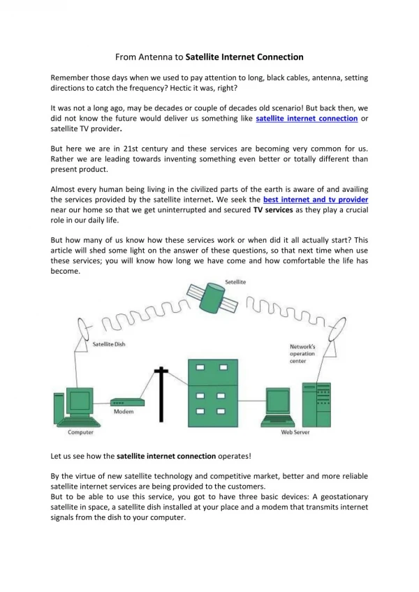
Car Rooftop Antenna for Satellite Radio Reception. Team 26: Joe Banasiak Jeremy Seuring. Introduction. Satellite radio currently operates from 2.32 to 2.345 GHz Two companies offer this service: Sirius: 2.32-2.3325 GHz, $12.95/month XM: 2.3325-2.345 GHz, $9.99/month

E N D
Car Rooftop Antenna for Satellite Radio Reception Team 26: Joe Banasiak Jeremy Seuring
Introduction • Satellite radio currently operates from 2.32 to 2.345 GHz • Two companies offer this service: • Sirius: 2.32-2.3325 GHz, $12.95/month • XM: 2.3325-2.345 GHz, $9.99/month • XM uses geostationary satellites with a line of site of about 30 deg. above the equator • Sirius uses geosynchronous satellites (elliptical orbits) with a line of site of about 60 deg. above the equator • Both companies use terrestrial repeaters which are used to carry signal where buildings block satellite signals
Terrestrial Repeater Terrestrial Antenna To Satellite Radio Receiver Satellite Patch Array Antenna Phase Shifter Power Divider Objective • Our goal is to create low-profile antennas for both satellites and terrestrial repeaters • Design of a loop antenna for receiving the vertically (linear) polarized terrestrial signal • Design of an array of microstrip patches for receiving the LHCP satellite signal • We will incorporate phase shifting in our array to demonstrate beam steering capabilities Block Diagram
Design Goals • Frequency of operation from 2.32-2.345 GHz • Satellite antenna gain of at least 2 dBi over elevation angles 20 to 90 degrees • Demonstrate beam steering over elevation angles • Satellite antenna needs to receive circular polarization • Terrestrial antenna gain of at least -1 dBi from 0 to 20 degrees elevation • Terrestrial antenna needs to receive linear polarization
Terrestrial Antenna - Loop • Loop Antenna • The loop antenna is ideal for keeping the design of our antennas low-profile • Theory • Loop antennas emit the desired endfire pattern for loops with a diameter of roughly /10. • Problems • For our frequency, the diameter would be 1.29 cm, this makes fabricating the antenna extremely difficult • Wire radius needs to be small compared to loop size
Terrestrial Antenna - Monopole • Solution • We decided to compromise our low-profile design by using a monopole antenna • Theory • Input reactance of dipoles is minimized when the length of the dipole is about 0.5, 1.5, 2.5, etc. This is desired to make the antenna efficient • Image Theory • Introducing a ground plane caused an image of the antenna above the ground plane to be created below the ground plane • This allows for monopole antennas of half the length of a dipole antenna, that look like the dipole. • The input impedance of the monopole will be ½ the input impedance of the dipole • The gain of the monopole will be twice the gain of the dipole
Terrestrial Antenaa - Monopole L=0.75 • Typical patterns of a monopole • We wish to have a pattern that has a wide endfire beam, so the desired length of our monopole is 0.25 L=0.25 L=1.25
Terrestrial Antenna - Monopole • Simulations – Ansoft HFSS9 • We simulated our monopole antenna with different lengths of the monopole around /4 to find the best length of the monopole • The ground plane needed to be at least /2 on each side to be effective, so we chose 8 cm.
Terrestrial Antenna - Monopole • Once simulations were complete, we plotted S11 for each monopole length and compared to find optimal length
Terrestrial Antenna - Monopole Fabrication • Cut ground plane and drilled a hole in its center • Place SMA connector with the probe feed and dielectric through the hole in the ground plane • Soldered the SMA connector to the underside of the ground plane, and cut the dielectric flush with the top of the ground plane • Solder additional length of wire to probe, to make the monopole longer than anticipated length • Connect monopole to Network Analyzer and cut the length of the monopole down so S11 is minimized in our frequency range
Terrestrial Antenna - Monopole • After fabricating the monopole, and looking at S11, we determined S11 wasn’t low enough • We decided making the ground plane larger may improve S11, so we re-simulated and found that a ground plane with each side 16cm improved S11 dramatically Ground plane length 16 cm Ground plane length 8 cm
Radiation Pattern Test Set-up • We obtained our radiation patterns using the anechoic chamber, the HP 8510 Network Analyzer, and 959 Spectrum v2.1 software • The anechoic chamber is a room with special padding that absorbs electromagnetic radiation, ensuring that the signal received by the gain horn comes directly from the antenna • We tested our antennas by rotating them 360 degrees in three different planes • Azimuthal plane (x-y) • Elevation angle 0 degrees plane (y-z) • Elevation angle 90 degrees plane (x-z)
Terrestrial Antenna - Monopole • Simulations results vs Testing <- Simulated -> <- Tested ->
Terrestrial Antenna - Monopole E(θ) • Fields, simulated vs tested E(θ) E(φ) E(φ)
Terrestrial Antenna - Monopole • Overall specs: • Maximum Gain : 4.822 dBi • HPBW : 50 degrees • Gain greater that -1dBi over elvation angles -12 < θ < 72 • Better than the specification of 0 < θ < 20 • Greater than 90% of power accepted over frequency range • Input Impedance : (59 – j*5)Ω
Design of Patch Antenna: Theory and Materials • Patch antennas resonate at ~λe/2, but must be designed shorter to account for fringing fields • The type of feed and feed location will affect the input impedance of the patch antenna • Feed location also determines types of EM polarizations radiated and received • Actual dimensions of patch depend effective permittivity of the substrate • Increase in εr decreases size, but increases surface waves • Increase in dielectric thickness increases bandwidth • Decided on εr= 2.2 (Rogers Duroid 5880) with thickness =3.175 mm based on tradeoffs and available materials
Design of Patch Antenna: Simulation and Optimization Initial Design • Used an available program to find general starting points for a matched feed position • Constructed square patch with side length of 40.8mm and feed position of 13 mm from nearest sides (such that the feed position is located on the diagonal of the square) • Simulated in HFSS over the range 2.3-2.6 GHz • S11 plot shows that the patch does not reach true resonance • VSWR is above 2 over the operating band – which results in less than 90% of the incident power entering the patch S11 of Original Patch dB Freq (GHz)
Design of Patch Antenna: Simulation and Optimization Initial Design Optimized Design • Set up an optimization in HFSS to find the best feed point and side length for resonance and matching • Varied side length and feed point • Compared Smith charts, S11 plots, and VSWR plots of the results to obtain optimized patch • Determined side length of 40.3 mm and feed position of 15.25 mm to be optimum design • VSWR under 1.4 over entire operating band results in over 97% of input power entering patch • Used an available program to find general starting points for a matched feed position • Constructed square patch with side length of 40.8mm and feed position of 13 mm from nearest sides (such that the feed position is located on the diagonal of the square) • Simulated in HFSS over the range 2.3-2.6 GHz • S11 plot shows that the patch does not reach true resonance • VSWR is above 2 over the operating band – which results in less than 90% of the incident power entering the patch S11 of Optimized Patch S11 of Original Patch Under -15 dB over entire operating band dB dB Resonance at 2.33 GHz (midband) Freq (GHz) Freq (GHz)
Design of Patch Array: Theory • Why choose an array? • Arrays allow an increase in gain and beam steering capability • Why a 3 x 3 array? • Beam direction capabilities increase with the number of elements, but so does complexity of feed network. A 3 x 3 will allow us to attempt beam steering while still having fairly simple power combination • Array Spacing • Half wavelength spacing allows for minimization of sidelobes in array pattern • Array equation: • Pattern Multiplication • Multiply the array factors and element pattern to find radiation pattern
Design of Patch Array: Fabrication • Build • We’ve shown single patch works, simulator ran out of available memory when attempting to simulate full 3 x 3 array • Used HFSS geometry to program milling machine to mill out 3 x 3 array on Rogers Duroid 5880 dielectric • Drilled feed points and soldered a coaxial feed to each element • Power Combination • Nine elements - one feed • Used one 2 to 1 and two 8 to 1 power combiners made available by Prof. Bernhard • Problem: Power dividers are very expensive, and most are very wideband, the ones we used worked for 2-18 GHz (we only need 2.32-2.345 GHz) • Solution: For this array to be produced the most effective solution is to custom design a 9 way power split. Wilkinson Power Divider Can extend 2-way split to either binary tree or a N-way split
Design of Patch Array: Test Results Network analyzer results for patch resonance and coupling • Typical S11 ~ -15 dB at 2.3325 GHz • Typical coupling for adjacent patches ~ -17 dB • Typical coupling for diagonal patches ~ -23 dB (Reflection) (Adjacent Coupling) (Diagonal Coupling) • More than 90% power accepted over entire operating band • ~97% power accepted at 2.3325 GHz
Design of Patch Array: Test Results Max Gain: 10.2 dBi Axial Ratio: 1.4 dB Side Lobe Level: -5 dBi HPBW: 30 degrees E(θ) E(φ)
Design of Phase Shifter: Theory • Original Plan: To purchase phase shifters for the antenna elements to demonstrate beam steering ability • Problem: Phase shifters are very expensive and we would need 9 of them. Most phase shifters cover a large bandwidth • Solution: Build phase shifting lines for 3 discrete steering angles • Chosen Steering Angles: • θ = 70, φ = 0 (Along the x-axis) • θ = 30, φ = 90 (Along the y-axis) • θ = 70, φ = 30 (Off-axis) The necessary element phasing can be calculated with the following equation: knm = -k(ndsin(θ)cos(φ)+mdsin(θ)sin(φ)) • n is the element position along the x-direction • m is the element position along the y-direction • d = λo/2 • The delay lines were designed with lengths to match the calculated delays • Converted from delay length in radians to centimeters • Originally set reference element line length to λe • HFSS gave inaccurate results due to length of line, redesigned lines with reference length = λe /2
Design of Phase Shifter: Simulation & Fabrication • Simulated phase lines in HFSS, made necessary corrections • After final simulations all phase lines within 1 degree of desired phase length • Fabricated the lines with three lines to a feed and left connection gaps so we could solder the corresponding line for each beam steering direction
Design of Phase Shifter: Testing X-axis lines Desired Phase Delay Network analyzer results Y-axis lines Desired Phase Delay Network analyzer results Off-axis lines Desired Phase Delay Network analyzer results • X-direction lines in proper range or off by similar relative phase • Y-direction lines differ more, but are off by relatively similar values • Off-axis results far from desired did not test radiation pattern
Design of Phase Shifter: Testing X - Direction Radiation Patterns in dBi Max Gain: 8.2 dBi Axial Ratio: 2.1 dB Side Lobe Level: 0 dBi HPBW: 34 degrees E(θ) E(φ)
Design of Phase Shifter: Testing Y - Direction Max Gain: 9.4 dBi Axial Ratio: 2.1 dB Side Lobe Level: -5 dBi HPBW: 35 degrees E(θ) E(φ)
Function Test • We ordered an XM radio tuner and connected our antennas to it • The microstrip array antenna received well • The array needed to be pointed toward the south to pick up a signal. • On our demo day, we were located at Everitt’s shipping doors. We noticed that we were able to receive a signal when the array was pointed toward Talbot Lab, showing that the satellite signal was being reflected. • Monopole antenna performed well • We were able to pick up a signal, with almost any orientation of the antenna on a clear day when not surrounded by buildings. This demonstrated the monopoles large beam width.
Recommendations • Build narrow band power dividers to reduce the cost of the antennas • Steer beam by mechanical means rather than using phase shifters • To steer beam effectively, need many different phase shifts • Would allow smaller array or single element • Design different layout of patches so that beam steering is not needed • Requires circuitry to select the appropriate patch • Gain of each patch needs to be large enough • Encase antenna in material such as radome to shrink the size • Construct housing for antenna for protection Thanks to Prof. Bernhard’s group for materials and guidance Special thanks to Greg Huff