Download
1 / 26
260 likes | 488 Vues
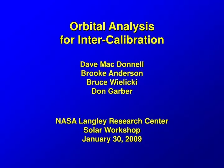
Orbital Analysis for Inter-Calibration Dave Mac Donnell Brooke Anderson Bruce Wielicki Don Garber NASA Langley Research Center Solar Workshop January 30, 2009. CLARREO Crossing Below Aqua 700km. Aqua MODIS, CERES, or AIRS Crosstrack Scan . D. Garber LaRC, 7/07. CLARREO 100 km nadir fov.

E N D
Orbital Analysis for Inter-CalibrationDave Mac Donnell Brooke Anderson Bruce WielickiDon GarberNASA Langley Research CenterSolar WorkshopJanuary 30, 2009
CLARREO Crossing Below Aqua 700km Aqua MODIS, CERES, or AIRS Crosstrack Scan D. Garber LaRC, 7/07 CLARREO 100 km nadir fov Time to Achieve Viewing Angle Matches: 40 seconds per 100km orbit altitude Difference: 140 seconds above
Top View: CLARREO under-flight of Aqua Aqua MODIS, CERES, or AIRS Crosstrack Scan CLARREO 100 km nadir fov Angle Pointing (zenith, azimuth) is required to obtain any calibration matches beyond those at nadir. Options: pointable instrument, pointing table, or S/C reaction wheels D. Garber LaRC, 7/07
Orbital Analysis • All orbits are modeled at a 600 km altitude • Selected based on its separation from NASA missions at 705 km and NOAA missions at 824 km • Altitude separation drives the slew rates during intercalibration • The altitude may be changed to above the key intercalibration targets altitudes ( i.e. 924 km) • Orbit inclinations angle are selected based on the precession behavior and the global coverage. • 90 degree inclination – 0 precessions per year • 74 degree inclination – 2 precession per year (at 600km) • 83 degree inclination – 1 precession per year (at 600km) • 97.8 degree inclination – Sun Synch (-1 precession per year @ 600km) • Ground track repeat avoidance • The ground track repeat cycle is set to greater than 50 days
Maximum Slew Rate versus Altitude Difference 3°/second for CLARREO to Aqua
Precession Rate Trade Space 600km/83° 600km/74.2° 600km/90°
Sun-Synchronous with respect to CLARREO 600km/74.2° Sun-Synch CLARREO 600km/74.2°
Sun-Synchronous with respect to CLARREO 600km/83° Sun-Synch CLARREO 600km/83°
Sun-Synchronous with respect to CLARREO 600km/90° Sun-Synch CLARREO 600km/90°
Two CLARREO Satellites 600km/90° CLARREO 1 CLARREO 2
Three CLARREO Satellites 600km/90° CLARREO 1 CLARREO 2 CLARREO 3
Solar Intercalibrations with Aqua600km by 74 degrees Opportunities - 737 Nadir/2278 Pointing
Solar Intercalibrations with Aqua600km by 83 degrees Opportunities - 926 Nadir/3631 Pointing
Solar Intercalibrations with Aqua Two Satellites at 600km by 90 degrees Opportunities (each) - 713 Nadir/2424 Pointing
Solar Intercalibrations with AquaThree Satellites at 600km by 90 degrees Opportunities (each) - 713 Nadir/2424 Pointing
Solar Intercalibrations with Aqua600km by 74 degrees and 90 degrees
Solar Intercalibrations with Aqua600km by 90 degrees and Sun-Synchronous Opportunities - 737 Nadir/2278 Pointing
Annual Beta-Angle CycleTwo Satellites at 600km by 90 degrees
Annual Beta-Angle CycleThree Satellites at 600km by 90 degrees
Spacecraft Configuration Challenges • With spacecraft orbits that result in positive and negative beta-angles, the sun will eliminate both sides of the spacecraft. • The spacecraft will likely require a 180 degree yaw when the beta-angle crosses zero. • This will maintain one side of the spacecraft as the cold side, which is suitable for radiator placement. • The solar array could maintain favorable views to the sun for power generation.
Summary • The orbital analysis of the four orbital plane options are modeled and can be adjusted as needed. • Pointing capability will increase the number of sample opportunities by 3 to 4 times. • Assuming 10 seconds per sample and 2 seconds buffer • The beta-angle range will likely force the spacecraft to change the orientation of the spacecraft. • Nadir pointing will be maintained. • Yaw of 180 degrees is likely