Download
1 / 29
340 likes | 1.56k Vues
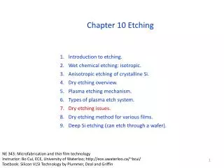
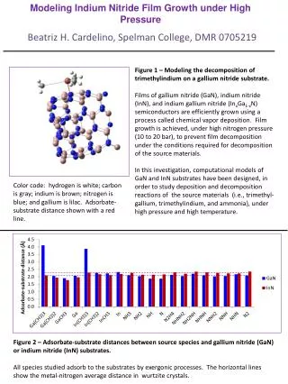
Photoelectrochemical Wet Etching of Gallium Nitride. Jack Huynh Jerry Hitchcock & Newton Cheng present. University of Illinois, Champaign-Urbana Department of Electrical and Computer Engineering ECE 345, Senior Design April 26, 2000. GaN Background and Application.

E N D
Photoelectrochemical Wet Etching of Gallium Nitride Jack Huynh Jerry Hitchcock & Newton Cheng present University of Illinois, Champaign-Urbana Department of Electrical and Computer Engineering ECE 345, Senior Design April 26, 2000
GaN Background and Application • Wide energy band gap (3.4 eV) • Useful optical properties • Optical applications: Blue LED’s, lasers, photodetectors • Chemically inert material • High power, high frequency device applications
Problems with GaN • Grown epitaxially on a sapphire or silicon-carbide substrate • High density of lattice defects due to lattice mismatches in GaN-substrate interface • Resistive to chemical wet etching due to chemical inertness
Problems with Dry Etching • Ion Bombardment commonly used • Lattice Damage • Nonselective Etching • Cost • Throughput
Advantages of Wet Etching • Selectivity • Cost • Throughput • No Lattice Damage • Anisotropic
Enhanced Wet Etching • Photoelectrochemical (PEC) • Appropriate UV Source • Applied Bias • Chemical Medium Selection • Specialized Holder • LabView Data Acquisition System • Mask
PEC Reaction • Dissolution Process • 2 GaN + 6 h+ 2 Ga3+ + N2 • 2 Ga3+ + KOH Reaction Products • Reaction Products • Soluble • Insoluble
PEC Wet Etch • Etch Time 20 Minutes • pH of KOH Solution (11, 12, 13) • UV Intensity (10mW / cm2, 20mW / cm2, 30mW / cm2) • Bias (0V, 1V)
Etch Rate Results for 0V Bias Etch Rates in angstroms/min.
Etch Rate Results for 1V Bias Etch Rates in angstroms/min.
Surface Morphology • Several different profiles • Smooth • Dislocation etching • Columnar nanostructure • Nanometer etch pit • Intermediate morphologies • Irregular etch pits • Follow regular evolutionary pattern
Smooth Morphology Occurs at low pH, low to mid-range intensity
Dislocation Etch Morphology Occurs at low pH, low to mid-range intensity
Columnar Nanostructure Morphology Occurs at mid to high pH, low to mid-range intensity
Nanometer Etch Pits Morphology Occurs at high pH, high intensity
Nanometer Etch Pit Formation • Positive uncompensated donor atoms • Columnar orientation • Macroscopic electric field • Increased etching between columns
Irregularly Shaped Etch Pits Occurs at high pH, low intensity
Morphology Trends at 0V S – smooth D – dislocation C – columnar nanostructures N – nanometer etch pits I – irregularly shaped etch pits
Morphology Trends at 1V S – smooth D – dislocation C – columnar nanostructures N – nanometer etch pits I – irregularly shaped etch pits
Conclusions • PEC Etching with applied Bias • Improves etch rates • Improves smoothness • Smooth Etch Conditions • pH below 12 • Light intensity up to 20mW / cm2 • High Etch Rate Conditions • pH between 12 and 12.5 • Light intensity of 30mW / cm2