Download
1 / 6
60 likes | 106 Vues
Get the best Orbital Mechanics help by expert writers of EssayCorp. We provide our services across the world at an affordable price. For any academic query contact us at contact@essaycorp.com. Some of our key features are:<br><br>100% plagiarism free work, On Time Delivery, 24*7 online support.

E N D
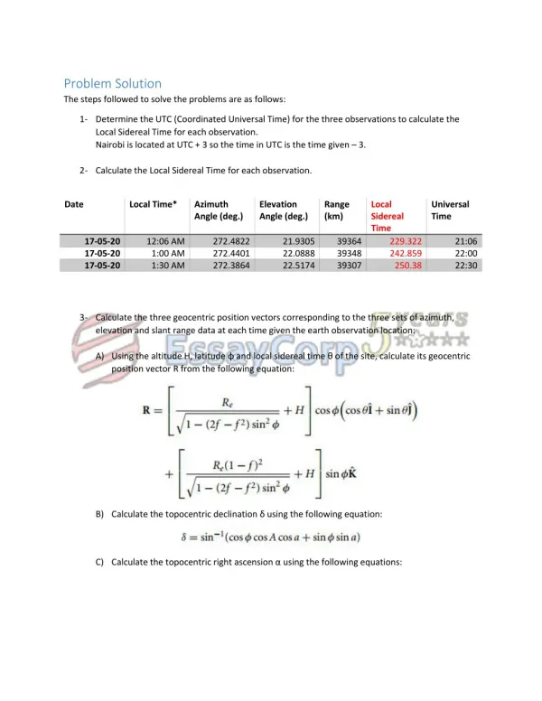
Problem Solution The steps followed to solve the problems are as follows: 1- Determine the UTC (Coordinated Universal Time) for the three observations to calculate the Local Sidereal Time for each observation. Nairobi is located at UTC + 3 so the time in UTC is the time given – 3. 2- Calculate the Local Sidereal Time for each observation. Date Local Time* Azimuth Angle (deg.) Elevation Angle (deg.) Range (km) Local Sidereal Time Universal Time 17-05-20 17-05-20 17-05-20 12:06 AM 1:00 AM 1:30 AM 272.4822 272.4401 272.3864 21.9305 22.0888 22.5174 39364 39348 39307 229.322 242.859 250.38 21:06 22:00 22:30 3- Calculate the three geocentric position vectors corresponding to the three sets of azimuth, elevation and slant range data at each time given the earth observation location: A) Using the altitude H, latitude φ and local sidereal time θ of the site, calculate its geocentric position vector R from the following equation: B) Calculate the topocentric declination δ using the following equation: C) Calculate the topocentric right ascension α using the following equations:
D) Calculate the direction cosine unit vector using the following equation: E) Calculate the geocentric position vector r using the following equation: The results obtained by MATLAB were as the following: 4- Applying Gibbs’ Method to the three obtained position vectors to get the velocity vector corresponding to the second position vector: - The result was as following: We take the initial r and v to be r2 and v2: 5- Knowing r and v the 6 COE could be obtained easily using the below flow graph [1] and the results were:
Since the eccentricity is between 0 and 1, the orbit is elliptical. For elliptical orbit the following equations were applied: Average angular velocity Mean Motion (Mean anomaly) The eccentric anomaly is then connected to the mean anomaly using:
This equation was solved numerically to obtain E with every Mean anomaly using fzero function from MATLAB. It applies newton’s method using the following function The true anomaly was then obtained by Then R and V were obtained by: These were then transformed to the geocentric frame using a transformation matrix. Circular, parabolic, and hyperbolic orbits are also found in the code but are not of our interest as our orbit is elliptical. The position and velocity vectors were forced to be calculated at t = 3600 s and it can be found in the last column (not drawn). They are as follows:
The orbit trajectory for one time- period: Important Notes: Only the file ‘Main_Orbital.m’ needs to be run to solve the problem, it iterates over time and draws the ellipse. It calls the script 'Final_r_v.m' which in turn obtains the initial velocity and position as stated above. Another method was applied called ‘Universal Kepler Equations’, it can be found in the MATLAB script ‘orbit_solve_draw.m’. Conclusion The orbit is an elliptical orbit with a very small eccentricity, (nearly circular). The object is orbiting in a prograde orbit; meaning that it is rotating in an opposite direction to the direction of rotation of Earth. In addition, the object is not expected to escape the orbit or collide with Earth, instead, it will remain in orbit. <REQU> - required output can be found in red.
References: 1- Orbital Mechanics for Engineering Students 2- Understanding Space: An Introduction to Astronautics 2nd 3- http://www.bogan.ca/orbits/kepler/orbteqtn.html 4- https://www.maplesoft.com/content/EngineeringFundamentals/49/MapleDocument_46/Orbita _Mechanics.pdf