Electricity Fundamentals
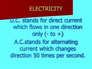
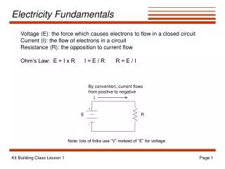
Electricity Fundamentals. Voltage (E): the force which causes electrons to flow in a closed circuit Current (I): the flow of electrons in a circuit Resistance (R): the opposition to current flow Ohm’s Law: E = I x R I = E / R R = E / I. By convention, current flows

Electricity Fundamentals
E N D
Presentation Transcript
Electricity Fundamentals Voltage (E): the force which causes electrons to flow in a closed circuit Current (I): the flow of electrons in a circuit Resistance (R): the opposition to current flow Ohm’s Law: E = I x R I = E / R R = E / I By convention, current flows from positive to negative I + E R - Note: lots of folks use “V” instead of “E” for voltage Kit Building Class Lesson 1
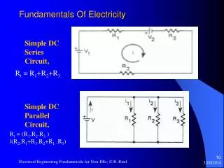
Kirchhoff’s Current Law Remember how to find the total resistance of resistors in parallel? For the circuit below, the same voltage is applied to both R1 and R2. Let’s multiply both sides of this equation by E: But Ohm’s law allows us to write this as: node This is Kirchhoff’s Current Law: the current entering a node in the circuit is equal to the sum of the currents leaving the node. Here, the current I flowing to the node divides. Some flows through R1 and the rest through R2. But the total through both is the same as the total in the circuit. I + E I1 R1 R2 I2 - Kit Building Class Lesson 1
Kirchhoff’s Voltage Law Remember how to find the total resistance of resistors in series? For the circuit below, the same current flows through both R1 and R2. Let’s multiply both sides of this equation by I: I But Ohm’s law allows us to write this as: R1 + This is Kirchhoff’s Voltage Law: the voltage added to the circuit by the battery is equal to the sum of the voltages consumed by the resistors. Here, some of the voltage from the battery is lost in each of the two resistors, and the sum of the voltage lost in the resistors is equal to the voltage of the battery. E - R2 Kit Building Class Lesson 1
Measuring Current Electric current is always measured by connecting an ammeter in series with the component through which you’d like to know the current. I Note that ammeters have polarity. Make sure you connect the + and - leads so that the current will flow through the meter from + to -. The + lead is closer to the + terminal on the battery, and the - lead is closer to the - terminal on the battery. + + A A - - + E I1 R1 R2 I2 - Kit Building Class Lesson 1
Measuring Voltage Voltage is measured as either: - the voltage drop across a component or part of the circuit, or - the voltage at a point with respect to ground I Always connect the voltmeter in parallel with the part of the circuit across which the drop in voltage is being measured. The + lead of the voltmeter is closest to the + terminal on the battery. If measuring with respect to ground, connect the - lead to the circuit ground (the negative terminal of the battery). + V R1 + - E + - V R2 - Kit Building Class Lesson 1
SW+40 Block Diagram SA612 SA612 NE5532 4 MHz Xtal Filter RX Mixer Product Detector BP Filter RF In/Out AF Amp RX (high) BP Filter VFO AF Out 3 - 3.05 MHz RX - TX = 800 Hz TX Filter, Amp ~4 MHz TX (low) TX Mixer SA612 Kit Building Class Lesson 1
SW+ Voltage Regulation D13 1N4001 78L08 U2 +12V C113 0.1 +8V Reg Q: What would happen if we hooked up the battery backwards? C102 0.01 The 78L08 voltage regulator accepts a range of input voltages and produces a fixed 8-volt output which is very stable. Capacitors C113 and C102 act to provide a path to ground for any RF component in the voltage line from other parts of the circuit. Note: capacitance values given on schematics as decimals are usually in mF, while those given as integers are usually given in pF. Example: “0.1” is 0.1 mF, while “47” is 47 pF (remember, 1,000,000 mF = 1 F, and 1,000,000 pF = 1 mF). Kit Building Class Lesson 1
78L08 Specifications Minimum Input Voltage: 10.5 Volts Maximum Current Draw: 100 mA Source: Texas Instruments Kit Building Class Lesson 1
Diode Basics I + + - - Reverse bias--no current flows (high resistance) Forward bias--current flows! (low resistance) 1N4001 1N4148 Anode Cathode Anode Cathode Kit Building Class Lesson 1
Diode Characteristics +IF +IF “Regular” Diode Zener Diode zener point -40 -20 -40 -20 +VF +VF 1 2 3 1 2 3 Constant breakdown voltage Reverse breakdown No current flows Forward bias Zener diodes work like “regular” diodes except that when the reverse breakdown voltage is reached, the zener diode will allow conduction but will keep the voltage drop across it constant. Zener diodes are usually reverse-biased in circuits to take advantage of this characteristic. Zener diodes are manufactured with a variety of values of breakdown (or zener) voltages. Conduction begins when forward bias is applied which exceeds a fairly low threshold (0.5 - 1 V). If reverse bias is applied, no current flows until reverse bias voltage exceeds the breakdown voltage, at which point current increases with reverse voltage. Kit Building Class Lesson 1
Quiz What will be the voltage at points A, B, C, and D? What will be the voltage drop across U2? What will be the current through C102? When you finish constructing this part of the circuit, measure these voltages. Are they what you expected? A B D13 1N4001 C D 78L08 U2 +12V C113 0.1 C102 0.01 Kit Building Class Lesson 1
Construction • Inventory all the parts in your kit--contact NN1G if you’re missing any parts • Install the following components: • C102, C113 • D13, U2 (make sure you observe correct polarity!) • Connector J4 • connect the 5.5mm/2.1mm coaxial jack to the wiring harness matching J4 (observe correct polarity--see NN1G’s instructions) • Test: • Apply 12 -15 V power to J4 • Measure voltage at D13’s cathode--should be less than the input voltage by around a half a volt or so • Measure voltage at pin 1 of J2’s location on the PC board (we haven’t installed J2 yet) -- should be 8.0 V Kit Building Class Lesson 1