Download
1 / 53
550 likes | 848 Vues
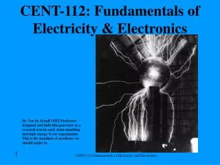
CHAPTER. Fundamentals of Electricity. 2. Instructor Name: (Your Name ). Learning Objectives. Relate electrical terms including voltage, current, and resistance to their hydraulic or pneumatic counterpart Explain the relationship among voltage, current and resistance in an electrical circuit

E N D
CHAPTER Fundamentals of Electricity 2 Instructor Name:(Your Name)
Learning Objectives • Relate electrical terms including voltage, current, and resistance to their hydraulic or pneumatic counterpart • Explain the relationship among voltage, current and resistance in an electrical circuit • Apply Ohm’s law to simple electrical circuits to determine an unknown voltage, current or resistance
Learning Objectives • Perform measurements of voltage, current and resistance using a digital multimeter (DMM) • Describe the concept of voltage drop across a resistance when current flows through the resistance • Demonstrate Kirchhoff’s voltage and current law through voltage and current measurements obtained from a series, a parallel, and a series-parallel circuit
Learning Objectives • Determine the total circuit resistance in a series, parallel, and series-parallel electrical circuit given the individual resistor values • Calculate voltage drops and currents draws in a series, parallel, and series-parallel circuit, given the individual resistor values and voltage source
Atoms, Protons and Electrons • Atoms are the smallest possible pieces of any known element • Atoms are made up of protons, electrons and neutrons • Protons have a positive charge and electrons have a negative charge • Like charges repel and opposite charges attract
Charges Suspended From Strings Figure 2-6 Charges suspended from strings.
Atoms, Protons and Electrons Atoms are like a solar system; protons are the sun with electrons orbiting like planets. Figure 2-7 Copper Atom.
Displacing Electrons • Rubbing two dissimilar materials can strip electrons from one material and add themto the other • One material has a positive charge (missing electrons) • One material has a negative charge (too many electrons) • An atom with an unequal number of protons and electrons is called an ion
Displacing Electrons • A material with an excess of electrons or protons will attract a material with the opposite charge • An atom with more protons than electrons is a positive ion • An atom with more electrons than protons is a negative ion • Electrons flow from a location where there is extra electrons to a location that is missing electrons
Figure 2-8 Opposite charges on the paper and comb cause an attraction.
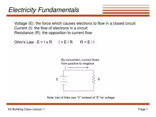
Electric Potential • Electric potential exists between two materials, one with excess electrons (negative charge) and one with an absence of electrons (positive charge) • Electric potential is know as voltage or electromotive force (EMF) • Voltage can be thought of as pressure in an electrical circuit • The unit of measurement of voltage or EMF is the volt • The symbol for volt is V (truck battery voltage is usually 12V)
Electron Flow • The flow of electricity is known as electric current • Current flow is the number of electrons passing a stationary point in a given period of time • 1 coulomb equals 6.25 billon-billion electrons passing a stationary point in a given period of time • Current is measured in amperes • The symbol for amperes is A
Direction of Current Flow • A battery has 2 terminals; positive and negative • The positive terminal is marked + and the negative is marked – • Conventional theory; positive to negative • Electron theory; negative to positive
Figure 2-9 Electron flow is like the movement of cars to the right, while conventional flow is like the movement of spaces to the left.
Direct and Alternating Current • Almost everything on a truck uses direct current (DC) • Direct current does not change direction or amplitude • Alternating current changes amplitude and direction of flow continually
Conductors • Conductors are made of materials that allow electron flow with little opposition • Conductors on trucks are usually made of copper • Free electrons are easily dislodged from the outer most band of an atom and into the outer most band of the atom next to it • The outer most band of an atom is called the valance band • Atom with one or two electrons in the valance band make good conductors
Figure 2-10 Electron flow is like marbles in a tube: a marble that enters the tube on the left is not the same marble that exits the tube on the right.
Conductors (continued) • Electron flow is believed to be an energy wave that flows through a conductor • The energy wave travels near the speed of light (186,000 miles/second) • The actual electrons only flow a few inches per hour • The energy wave is similar to the energy wave produced when a pool cue strikes a line of closely lined up pool balls and only the last ball rolls
Resistance • Resistance is the opposition to the flow of electric current • Ohm is the unit of measurement of electrical resistance • The symbol for ohms is the Greek letter omega (Ω) • Resistors are electrical components with a specific value of resistance
Wire Resistance • All electrical conductors have some resistance even though it may be a small amount • Wire resistance increases with the length of the wire, a 10mm wire has 10 times the resistance as a 1mm wire • A tungsten filament in a light bulb uses resistance to heat up and light when electrical current flows through it
Making Use of Wire Resistance Figure 2-15 Electrical resistance cause heat and light when electric current flows through the light bulb filament. Figure 2-14 Light bulb filament has a much smaller diameter than the wires connected to the light bulb causing an opposition to the flow of electric current.
Insulators • An insulator is a material that offers a great deal of resistance to the flow of electrical current • The resistance of an insulator is said to be very high • Insulators have five or more valence electrons • Plastic, rubber, and glass are examples of good insulators
Ohm’s Law • Increasing the voltage causes the electrical current flowing through a fixed value of resistance to increase • Increasing the resistance while keeping the voltage source held at a fixed value causes the electric current flowing through the resistance to decrease
Ohm’s Law (continued) • Voltage ÷ Resistance=Current • 1 Volt ÷ 1 Ohm = 1 ampere • E ÷ R = I • E = Voltage • R = Resistance • I = Amperes
Memorization Aid Figure 2-16 Ohm’s law memorization aid.
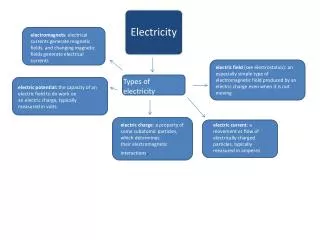
Electrical Maps • Circuits are the path that electrical current flows • Schematics are used to show the layout or relationship of electrical components • Schematics are also know as circuit diagrams or wiring diagrams • Electrical schematics use symbols to indicate electrical components found in an electrical circuit
Common Electrical Symbols Figure 2-17 Electric symbols used to construct electrical schematic.
Measuring Pressure • Most pressure gauges display the difference between atmospheric pressure and the unknown pressure and reads as PSIG; G= Gauge • Some gauges display the difference between an absolute vacuum and the unknown pressure and reads as PSIA; A= Absolute • A differential pressure gauge measures the difference between two different gauge ports
Measuring Voltage • Voltmeters are electrical diagnostic tools that read voltage • Voltmeters display the difference in electrical potential (voltage) between two points • Most common volt meters are multimeters capable of reading volts, amperes and resistance • Test leads are wires with probes that connect the volt meter to the circuit being tested
Typical Multimeter Figure 2-22 Digital multimeter.
Measuring Voltage (continued) • Test leads are typically colored red and black • The red lead is installed at the most positive point in the circuit • The black lead is installed at the most negative point in the circuit • Volt meters are connected to a circuit in parallel
Measuring Voltage With a Voltmeter Figure 2-24 Measuring Voltage.
Measuring Current • Current flow through a circuit is measured with an ammeter • An ammeter is typically included in a multimeter • Ammeters are connected in series in a circuit • Most multimeters have a specific plug for reading current • The circuit current can not exceed the maximum amperage rating of the ammeter
Measuring Current With an Ammeter Figure 2-26 Measuring current with an ammeter.
Tech Tip Modern DMM are fantastic tools but have fooled almost every technician at one time or another. One reason for this is just a miniscule amount of voltage present in a circuit when resistance is being measured can result in dramatic resistance measurement errors. The miniscule voltage can be generated by engine coolant or water in contact with dissimilar metals, as will be explained in more detail in later chapters. If resistance measurements do not make sense, measure the voltage that is present between the two points of which you want to know the resistance. If the DMM displays any voltage, your resistance reading will not be accurate.
Current Shunts and Amp Probes • A current shunt is a known low value of resistance placed in the circuit. • Voltage is measured across the shunt • Current can be calculated with Ohm’s law • Clamp on current probes measure the strength of the magnetic field surrounding a wire and converts it to a current value • Current probes may also be designed as an input device to a DMM • Clamp onprobes make troubleshooting easier because the circuit does not have to be opened to make a amperage reading
Clamp On Current Probes Figure 2-28 Clamp-on current probes.
Measuring Resistance • Resistance is measured with an ohmmeter • If the ohmmeter has a range setting, set to the highest range of unknown resistances • It is better to isolate the component from the rest of the circuit • If a negative resistance reading is obtained look for voltage on the circuit
A Pressure Differential Gauge Figure 2-33 Using a differential pressure gauge.
Measuring Voltage and Current in a Series Circuit Figure 2-40 Measuring voltage drop and current flow.
Increasing Resistance to 3 Ohms Figure 2-41 Increasing resistance.
Measuring Voltage Drops Figure 2-44 Difference in the voltage dropped across unequal series resistors.
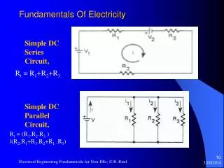
Series Circuit • Series circuits have only one path for current flow • The sum of all the voltage drops in a series circuit is equal to the source voltage • The total circuit resistance is the sum of all the resistance in the circuit
Parallel Circuits • Parallel circuits contain multiple paths for current flow • Voltage drops in a parallel circuit always equal the source voltage • The sum of the current flow in each branch of a parallel circuit is equal to the total current supplied by the voltage source • Adding additional parallel resistance decreases the total circuit resistance • Total circuit resistance in a parallel circuit is always less then the smallest resistor • To calculate total resistance in a parallel circuit use the product over the sum formula
Calculating Total Resistance in a Series Parallel Circuits Figure 2-50 Solved series-parallel circuit. Figure 2-49 Series-parallel simplification progression.
Metric Prefixes Figure 2-51 Common metric prefixes used in electrical system troubleshooting.
Three Resistors in Parallel Figure 2-52 Three resistors in parallel. Note the measured resistance value is less than any of the parallel-connected resistors.
Summary • A difference in electric potential between two points causes electrons to flow between the two points when a conductive pass is provided between them. Voltage is electrical potential and is measured in volts. Voltage can be thought of as pressure in a hydraulic or pneumatic circuit. • The flow of electrons is called current and measured in amperes. An ampere describes a quantity of electrons passing a stationary point per second. Electric current is like the fluid that flows in a hydraulic circuit.
Summary (continued) • The opposition of electric current flow is called resistance and is measured in ohms. • Ohm’s law mathematically describes the relationship between voltage, current, and resistance. Ohm’s law indicates that dividing the value of the voltage dropped across a resistance by the value of resistance in ohms yields the current flow through the resistance in amperes. Ohm’s law can be manipulated so that when any two quantities are known (voltage, current, or resistance) the third unknown quantity can be calculated.
Summary (continued) • A voltmeter is like a pressure differential gauge in that the difference in electrical potential between two points is being measured. A voltmeter is typically placed in parallel across a component to measure the voltage drop across the component. • An ammeter is like a flow meter in that the quantity of electrons passing a stationary point per second is being measured. An ammeter is always placed in series with the portion of the circuit that the current flow is being measured. Placing an ammeter in parallel with a component can damage the ammeter.