
Neutron
E N D
Presentation Transcript
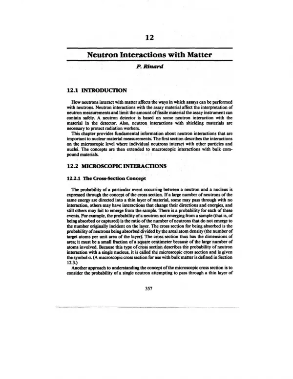
12 Neutron Interactions with Matter P. Rinard 12.1INT R ODUCT ION How neutrons interact with matter aflkcts the ways in which assays can be pdormed with neutrqs. Neutron interactions with the assay material affkct the interpretation of neutron measurements and limit the amount of fissilematerial the assay instrument can contain safely. A neutron detector is based on some neutron interaction with the material in the detector. Also, neutron interactions with shielding materials are necessary to protect radiation workeri. This chapter provides iimdamenial information about neutron interactions that are important to nuclear material measurements; The that section describes the interactions on the microscopic level where individ@ nuclei. The concepts are then extended to macroscopic interactions with bulk com- pound materials. !, neutrons, interact with other particles and 12.2 MICR OSCOPIC INT E R ACT IONS 12.2.1 The Cross-Section Concept The probability of a particular event occurring between a neutron and a nucleus is expressed through the concept of the cross section. If a large number of neutrons of the same energy are directed into a thin layer of material, some may pass through with no interaction, others may have interactions that change their directions and energies, and still others may tbil to emerge *m the sample. There is a probability for each of these events. For example, the probability of a neutron not emerging from a sample (that is, of being absorbed or captured) is the ratio of the number of neutrons that do not emerge to the numtwr originally incident on the layer. The cross section for being absorbed is the probability of neutrons being absorbt+ di~ded by the anal atom density (the number of target atoms P& unit area of the layer): @e cross section thus has the dimensions of -, it must be a small flaction of a sqyiye centimeter becausk of the large’number of atoms involved. Because this type of c@# &ztion ,flescribestde probability ‘ofneutron interaction with a single nucleusj it is &Hledthe microscopic cross section and is.given the symbol C.(Amacroscopic cross section for use with bulk mdtter isdefined in Section 12.3.) ~other approach to wderstanding the concept of the microscopic cross section is to consider the probability of a single neutron attempting to pass through a thin layer of 357 -...— —,
P.Rinard 358 material that has an area A and contains N target nuclei, each of cross-sectional areas. The sum of all the areas of the nuclei is Ns. The probability of a single neutron hitting one ofthese nuclei isroughly the ratio ofthe total target area Ns to the area ofthe layer A. In other word$ the probability of a single neutron having a collision with a nuckus is Ns/A or (N/A)s, the areal target density timess. On the atomic level, however, cross sections for neutron interactions are not simply the geometrical cross-sectional area of the target. Byreplacing thiss by the a of the preceding paragraph, a might be thought of as an effective cross-sectional area for the interaction. The cross section for the interaction retains the dimensions of area thats had. The physical cross-sectional area s of a heavy nucleus is about 2 X 10-24 cm2. Interaction cross sections for most nuclei are typically between 10-27and 10-21cm2. To avoid the inconvenience of working with such small numbers, a different unit of area is used the barn, denoted by the symbol b. It is defined to be 10-24 cm2, so that the physical cross-sectional area of a heavy nucleus is about 2 b. Many neutron interaction cross sections range between 0.001 and 1000b. Each type of event has its own probability and cross section. The probability of each type of event is independent of the probabilities of the othe~ so the total probability of any event occurring is the sum of the individual probabilities. Similarly, the sum of all the individual cross sections is the total cross section. 12.2.2 The Energy-Velocity Relationship for Neutrons Cross-section magnitudes are strong fimctions of neutron energy, as discussed in Section 12.2.4.Asa preliminary to that discussion, this section describes the relationship between neutron energy and velocity. This connection is important not only for understanding cross sections but also for estimating the time that neutrons are present in regions such as those found in assay instruments. The classical expression for kinetic energy, E = mv2/2, is sufficiently accurate because even a kinetic energy of 100MeV is still only about one-tenth of the rest-mass energy of a neutron (939.55 MeV). For velocity v in meters per second and kinetic ene~ Ein MeV, ,, E = 5.227 X 10-ls # (12-1) and v = 1.383 X 10⁷E1~. (12-2) Figure 12.1 shows a graph of these equations for ready use. The graph show example, @t a.1-MeV neutron has a speed of 1.383 X 10⁷m/s and therefore willcross a 15-cm~ple region in a typical assay instrument in about 11ns. A thermal neutron with an ene~ of0.025 eV(seeSection 12.2.3)has a speed of 2187 m/s and willcross the same 15+ region in about 70 ps. for —.
359 NeutronInteractions withMatter 1on- I I I I I I I I I 107- ~ ~ > ~ o 2 ill > 106 – 1(F – 104 - Fig.12.1 Graphshowingtherela- tionshipbetweena neu- tron’sspeedand itskinetic energy. 103 10-6 10-7 10-13 10-510-4 10’ 102 lo-2 101 loll 10-3 NEUTRON ENERGY (MeV) 12.2.3 Types of Interactions A neutron can have many types of interactions with a nucleus. Figure 12.2shows the types of interactions and their cross sections. Each category of interaction in the figure consists ofallthose linked below it. The total cross section Ctexpresses the probability of any interaction taking place. Asimple notation can be used to give a concise indication ofan interaction ofinterest. If a neutron n impinges on a target nucleus T, forming a resultant nucleus R and the release of an outgoing particle g, this interaction is shown as T(n,g)R. The heavy nuclei are shown outside the parentheses. To denote a type of interaction without regard for the nuclei involved, only the portion in parentheses is shown. An example of an (n,p) reaction is‘B(n,p)5Be. An interaction may be one of two major types scattering or absorption. When a neutron is scattered by a nucleus, its speed and direction change but the nucleus is left with the same number of protons and neutrons it had before the interaction. The nucleus will have some recoil velocity and it maybe lefi in an excited state that will lead to the eventual release of radiation. When a neutron is absorbed by a nucleus, a wide range of radiations can be emitted or fission can be induced. Fig.12.2 Variouscategoriesofneutron interactions.Thelettersseparated bycommas intheparenthesesshowtheincomingandoutgoing particles.
P. Rinard 360 Scatteringevents can be subdivided into elastic and inelastic scattering. In elastic scattering the total kinetic energy of the neutron and nucleus is unchanged by the interaction. During the interaction, a fkaction of the neutron’s kinetic energy is trans- ferred to the nucleus. For a neutron of kinetic energy Eencountering a nucleus of atomic weightA, the average energy loss is 2EA/(A+ 1)2.This expression shows that in order to reduce the speed of neutrons (that is, to moderate them) with the fewest number of elastic collisions target nuclei with small A should be used. By using hydrogen, with A = 1,the average energy loss has its largest value of E/2. A neutron with 2 MeV of kinetic energy will (on the average) have 1 MeV left after one elastic collision with a hydrogen nucleus, 0.$ MeV after a second such collision, and so on. To achieve a kinetic energy of only 0.025 eV would take a total of about 27 such collisions. (A neutron of energy 0.025 eV is roughly in thermal equilibrium with its surrounding medium and is considered a “thermal neutron.” From the relation E = kT where k is Boltzmann’s constant, an energy E of 0.025 eV corresponds to a temperature T of 2&C.) In general, after n elastic collisions, the neutron’s energy is expected to change tlom ~ to En = ~(A2+l)/(A+l)2~. To reach En from l~(A2+l )/(A+l )2]collisions, on the average. Table 12-1’ gives examples of the number ofcollisions required to “thermalize” a 2-MeV neutron in some materials. Inelastic scattering is similar to elastic scattering except that the nucleus undergoes an ,internal rearrangement into an excited state from which it eventually releases radiation. The total kinetic energy of the outgoing neutron and nucleus is less than the kinetic energy of the incoming neutron; part of the original kinetic energy is used to place the nucleus into the excited state. It is no longer easy to write an expression for the average energy lossbecause it depends on the enexgylevels within the nucleus. But the net effect on the neutron is again to reduce its speed and change its direction. If all the excited states of the nucleus are too high in energy to be reachixl with the energy available fmm the incoming neutron, inelastic scattering is impossible. In particular, the hydrogen nucleus does not have excited .sta~ so only elastic scattering can occur in that case. In general, scattering moderates or reduces the energy of neutrons and provides the basis for some neutron detectors (for example, proton recoil detectors).’ EO thus requires n = log(En/~)/ Table 12-1. Avemge number of col- lisions required to reduce a neutron’s ene~ from 2 MeV to 0.025 eV by elastic scattering Number of Collisions Atomic Weight Element Hydrogen Deuterium Helium Beryllium Carbon Uranium 1 2 4 9 27 31 48 92 119 2175 12 238
Neutron Interactions with Matter 361 Instead of being scattered by a nucleus, the neutron may be absorbed or captured. A variety ofemissions may follow, as shown in”Figure 12.2.The nucleus may rearrange its internal structure and release one or more gamma rays. Charged particles may also be emitted the more common ones are protons, deuterons, and alpha particles. The nucleus may also rid itself of exeess neutrons. The emission of only one neutron is indistinguishable from a scattering event. If more than one neutron is emitted, the number of neutrons now moving through the material is larger than the number present before the interaction; the number is said to have been multiplied. Finally, there maybe a fission event, leading to two or more fission fragments (nuclei of intermediate atomic weight)and more neutrons (see Chapter 11). Many safeguards instruments have neutron detectors that use an absorption reaction as the basis of the detection technique. The lack of an electric charge on the neutron makes direct detection difflcul$ so the neutron is first absorbed by a nucleus, which then emits a charged particle (such as a proton or deuteron). Helium-3, uranium-235 and boron- 10 are commonly used in deteetors because they have large absorption cross seetions for the production of charged particles with low-speed neutrons. When moderation alone is desired, absorption should be avoided. For example, hydrogen is a better mqderator than deuterium (that is, it requires fewer collisions to achieve a particular low speed), but it also has a larger absorption cross section for neutrons. The net effect is that deuterium will yield more thermal neutrons than hydrogen and may be the preferred moderating material. The cross seetions associated with the various interactions described above can be designated by the following notation cft = total cross section (OS+ Oa) OS= total scattering cross section (Oel+ Oi) Celor On,n= elastic scattering cross section ~i or Cn,nt= inelastic scattering cross section Oaor csc= absorption or capture cross section %e= nonelastic cross section, at — oel ‘n,?= radiative capture cross section of or on,f = fission cross section on,p = (n,p) reaction cross section. 12.2.4 Energy Dependence of Croaa Sections Allof the cross sections described above vary with neutron energy and with the target nucleus, sometimes in a dramatic way.This section gives some generalizations about the energydependence ofcross seetions and shows data (Ref. 1)for a few important nuclei. Figure 12.3is the total cross section for 239Pufor incident neutrons of O.001-eVto 10- MeV energy. Note that as a general rule the cross section decreases with increasing energy. At low energies, below 1 MeV, the elastic cross section is nearly constant, whereas the inelastic scattering cross section and absorption cross seetions are propor- tional to the reciprocal of the neutron’s speed (that is, l/v). So at low energies the total cross section can be nearly constant or decreasing with energy,depending on which type of event dominates. For example, in 239Puthe inelastic cross seetion dominates and the total cross section decreases as l/v. Similar behavior is observed for most light and
P.Rinard 362 ,~~ 103 10’ 10’ 10 to’ 10 10’ 10: ‘9’ 1 NEuTRON ENERGY teV) Fig.12.3 Totalneutroncrosssectionof ‘%%. intermediate weight nuclei as well. Figures 12.4and 12.5illustrate the low-energy total cross-section behavior of boron and cadmium. The unusually high absorption cross sections of these two materials make them usefid as thermal-neutron poisons. At higher energies the cross section may have large peaks superimposed on the I/v trend These peaks are called resonances and occur at neutron energies where reactions with nuclei are enhanced. For example, a resonance will occur if the target nucleus and the captured neutron form a “compound” nucleus, and the energy contributed by the neutron is close to that of an excited state of the compound nucleus. In heavy nuclei, large and narrow resonances appear for neutron energies in the eV range. For energies in the keV region the resonances can be too close together to resolve. In the MeVregion the resonances are more sparse and very broad, and the cross sections become smooth and rolling. For li@ nuclei, penances and are broad and relatively small. For nuclei with intermediate weights (such as appear only in the MeV region 10,000 I I I I I I 5,000 If Z 1,000 – 500 - z ~ In m 100 – $ o 50 – 10 – I I I I I I 5 Fig.12.4 Low-energytotal neutroncrosssection ofboron(Re$ 1). 1.0 100.0 0.010 NEUTRON ENERGY (eV)
363 NeutronInteractions withMatter 200,000 I I I I I 1 50,000 – ~ $ ~ z o i= $ m m W o a o 10,000 – 5,000 – 1,000 – 500 — 50 — 10 – 5– 3 I I I I I 0.0001 0.001 0.01 0.10 1.0 10.0 NEUTRON ENERGY (eV) Fig.12.5 Low-energytotal neutroncrosssectionofcadmium (Rej 1). cadmium, nickel, iron), resonances can be found below 1keV. These resonances have heights and widths between those of light and heavy nuclei. Some exceptions to the general trends exist in ‘H and *H wheq there are no resonances at all and in nuclei with “magic” numbers of protons or neutrons where the behavior may be similar to that of light nuclei despite the actual atomic weight. In practice, it@necessary to relyon tables ofcross sections for the nuclei of interest because there is no convenient way to calculate cross sections. Some microscopic cross sections are included in the second table in Section 12.3. Some neutron-induced fission cross sections important for nondestructive assay are shown in Figure 12.6.The fissileisotopes 235Uand ‘9Pu have largecross sections (about 1000b) for fission by thermal or near-thermal neutrons. For fission by fast neutrons (10 keVto 10MeV),these cross sections are reduced to 1to 2b. The fertile isotopes 23SUand 2% have negligible fission cross sections for low-energy neutrons but exhibit a “threshold” near l-MeV neutron energy. Above 1MeV the fission cross sections of the fertile isotopes are comparable to those of the fissile isotopes. 12.3 MACR OSCOPIC INT E R ACT IONS 12.3.1 h@XWCOPiC tiOSS ~tiO12S Although study of the interactions of a neutron with a single nucleus on the microscopic scale provides a basis for understanding the interaction process, measure- ments are actually performed with thick samples that often contain a mixture of elements. These additional features are described by using the macroscopic cross sections appropriate for bulk materials. —-.—, -—---- -.
P.Rinard 364 I 50W . I \ \ \ \ \ g 1000 — J zoi= & w UY ~ K v 100 — \\ \\ \ \ ~ L’1 \ \ \ \ I I 20 - 0.001 1.0 0.1 0.01 NEUTRONENERGY (eV) 10.0 - I I I 23s” --~ Ko 228” I I 0.01 108 107 I@ Id 104 NEUTRON ENERGY (eV) Fig. 12.6 Fissioncrosssectionsjbrsome importantfissile(235U, 239Pu) andj2ertile(238U,2@Pu)isotopes(Ref1). The definition of the macroscopic cross section arises from the transmission of a parallel beam of neutrons through a thick sample. The thick sample can be considered to be a series of atomic layerq for each layer we can apply the results found with the microscopic cross-section concept. Byintegrating through enough atomic layers to reach a depth x in the sample,.lhe intensity I(x) of the uncollided neutron beam is (12-3) I(x) = ~ e-NW
365 NeutronInteractions withMatter where ~ is the intensity of the beam before it enters the sample, N is the atom density, and q is the total cross section. Figure 12.7shows the uncdided a ~el ~ * it IMssesthin@ a thick laYer of matter. Note that the ilaction transmitted without collisions, I(x)/~, depends on the energy of the neutrons through the energy dependence of the microscopic total cross-section at. An expression similar to Equation 12-3 is used for gamma-ray attenuation. In that ease, low~nergy gamma rays m very likely to be absorbed and thus removed not only from the parallel beam but tlom the material entirely. With neutrons at low energies, elastic scattering is the most likely event. Although Equation 12-3gives the intensity of the neutrons that have had no interaction up to a depth x,the actual number of neutrons present that ean be detected may be much larger because of multiple scatteri~ multiplication, or fini~ detector acceptance angle. The total macroscopic cross section is ~ = NtJt. Zt has dimensions of cm-l (see Equation 12-3above) and is analogous to the linear attenuation coefficient for gamma rays. Ifonly a particular type of intemction is of interestj a macroscopic cross section for it alone can be defined using its microscopic cross section in place of the total cross section. For quantitative calculations, the concept of macroscopic cross section is less used than the analogous gamma-ray linear attenuation coefficient because of the complications of multiple scattering and other effects mentiond, ~ph. intensity remaining in in the previous ) I I 4 l(x) Fig.12.7 The intensity ofaparallelbeam decreases exponentially as itpasses through a thick layer of matter. of uncoilided neutrons ....-...... ..-.... —-.—.—
P. Rinurd 366 If the sample is a compound instead of a simple element, the total macroscopic cross section is the sum of the macroscopic cross sections of the individual elements (12-4) z =x~+x~+x~... . The atom density Ni of each element i is given by Ni = pNa nJM (12-5) wherepisthe density of the compound, M is the molecular weight of the compound; Na is Avogadro’s number, 6.022 X 1&3 atoms/mole, and ni is the number of atoms of element i in one molecule. From Equations 12-4 and 12-5 the general form of the macroscopic cross section can be written as @Ja I = ~(nlol + n202 -k n3c3 + ...) . (12-6) As an illustration of these equations, the total macroscopic cross section for l-MeV neutrons in ‘tU02 (density 10g/cm3, molecular weight 270) is calculated from the data in Table 12-2. Table 12-2.Nuclear data for ‘woz q at 1MeV (b) 6.84 7.10 8.22 Isotope 235u 23Su 160 ni 0.007 0.993 2.~ ~ = (10)(0.6022) t 270 [(0.007)(6.84)i- (0.993)(7.10)+ 2(8.22)]= 0.525 cm-l . (12-7) Powers of 1@4and 10–24have been cancelled in Avogadro’s number and in the cross- section values. These cross-section values were taken from Table 12-3(Ref 2),which is a compilation of microscopic and macroscopic cross sections at two neutron energies, 0.025eV (thermal) and 1MeV. 12.3.2 Mean Free Path and Reaction Rate A very descriptive feature of the transmission of neutrons through bulk matter is the mean-fi’ee-path length, which is the mean distance a neutron travels between interac-
367 NeutronInteractions withMatter tions. It can be calculated from Equation 12-3with Nat replaced by Zt. The mean-free- path length k is A = Ijzt , (12-8) the reciprocal of the macroscopic cross section. For the case of l-MeV neutrons in U02 calculated above, a macroscopic cross section of 0.525 cm–l implies a mean-free-path length of 1.91cm. The mean-free-path length has many qualitative applications in assay instruments and shielding. (a) If the mean-free-path length of neutrons emitted by a sample in a passive assay instrument is long compared to the dimensions of the sample, it is likely that most of the neutrons willescape from the sample and enter the detection region. (b) If the number of collisions required to thermalize a neutron is known, the necessary moderator thickness of a shield can be estimated. (c) If the thickness of a shield is many times the mean-free-path length of a neutron trying to penetrate the shield, then the shield fulfills its purpose. (Because the mean-free-path length is a function of the neutron’s energy, the actual calculation is not so simple.) Acloselyrelated concept is that of the reaction rate. When traveling with a speed v, a neutron has an average time between interactions of %/v. The reaction rate is the frequency with which interactions occur: vfk, or v~t. In uranium oxide, for example, a 1- MeV neutron will have a reaction rate of 7.26 X 10⁸per second (from Equations 12-2 and 12-7).This does not mean, however, that in one second there will be that many reaction$ with each collision the neutron’s energy decreases and the cross section changes, thereby altering the instantaneous reaction rate. The paths of neutrons in matter can be simulated with Monte Carlo calculations. Figure 12.8shows a few paths for neutrons with 1MeV of energy entering cylinders of different materials. The mean-free-path length depends on both the type of material and the energy of the neutron. After each collision, the energy is decreased and the mean- free-path length isaffectedaccordingly. Figure 12.8showsthat a cylinder ofpolyethylene is more effective in preventing the transmission of neutrons than a cylinder of heavy metal. A neutron loses most of its energy by colliding with the light elements in polyethylene and then the mean-free-path length becomes small as the cross sections increase. An important effect of polyethylene is that it seemingly retains a large fraction of the neutrons near a certain depth; these neutrons have had enough collisions to lose nearly all their kinetic energy. If a thermal-neutron detector is placed in this region, the chance of detecting neutrons is optimized. 12.4E F F E CT S OF MODE WiTION IN BUL K MAT T E R It is otlen a design goal to reduce or moderate the speed of neutrons in the sample region or the detector region or both. Recalling the general l/v trend of interaction cross sections (Figures 12.3through 12.6),the purpose of the reduction in speeds is to increase the probability of an interaction. In other regions, it may be desirable to hinder interactions by choosing materials that are poor moderators or by adding low-energy neutron absorbers to remove neutrons once they become moderated.
w m 00 Table12-3.Neutroncrosssectionsofcommonmatenalsa CrossSectionsb E = 0.0253eV E=l MeV 2* (cm-i) Atomicor Molecular Weight 27 10 11 9 12 40.08 112 35.45 63.55 19 56 157.25 1 2 3 4 6 7 24.31 55 14 23 59 16 204 Density (g/cm3) 2.7 2.3 2.3 9.0 1.9 1.55 8.7 Gas 8.94 Gas 7.9 7.95 Gas Gas Gas Gas 0.534 0.534 1.74 7.2 Gas 0.971 8.9 Gas 11.34 Xa Material Al B B Be c NatCa cd NatCl NatCu F Fe NatGd H H He He Li Li NatMg Mn N Na Ni 0 Pb aRefl2. bAzerovaluemeanszerotothenumberoffiguresshown. (Cri%) (% $) (cm-l) ;) 2.37 2.68 2.13 3.25 2.58 1.14 6.50 2.30 3.40 3.15 5.19 7.33 4.26 2.87 2.87 7.08 1.28 1.57 2.66 3.17 2.39 3.17 3.66 8.22 4.39 %) (C3-’) 0.000 0.0262 0.000 0.0018 0.000 0.0001 0.0027 Gas 0.0009 Gas 0.0003 0.0068 Gas Gas Gas Gas 0.0123 0.0000 0.0000 0.0002 Gas O.0000 0.0001 Gas O.0001 1.61 0.232 0.000 0.189 0.000 0.003 0.000 0.004 0.058 0.0005 0.011 0.000 0.003 0.223 0.000 0.000 0.879 0.000 0.230 0.000 0.001 0.003 0.021 0.000 0.0008 0.000 0.0033 0.097 533 0.665 3.82 0.472 0.081 115.5 Gas 1.06 Gas 1.19 1496 Gas Gas Gas Gas 50.3 0.053 0.150 1.14 Gas 0.100 2.10 Gas 0.381 0.014 532 0.0006 0.0060 0.0003 0.101 115.2 Gas 0.322 Gas 0.217 1491 Gas Gas Gas Gas 50.2 0.0017 0.0027 1.04 0.143 0.371 0.268 1.96 0.246 0.027 0.304 Gas 0.288 Gas 0.441 0.223 Gas Gas Gas Gas 0.069 0.072 0.115 0.250 Gas 0.081 0.322 Gas 0.147 3845 3843 5.28 6.35 4.95 3.46 0.005 0.010 0.003 0.433 2470 2462 50.2 12.5 3.72 14.07 33.4 3.80 0.010 2.56 49153 48981 30.62 4.25 0.33 0.000 5336 5337 0.86 0.000 938 937 1.16 3.47 14.5 12.22 3.92 23.08 3.87 11.40 0.036 0.063 13.2 1.9 0.529 4.58 0.000 0.18 Gas 0.0134 0.416 Gas 0.0060 !% & z& &
Table12-3.Neutroncrosssectionsofcommonmaterials (continued) CrossSectionsb E=l MeV E = 0,0253eV Atomicor Molecular Weight 238.05 239.05 240.05 241.06 242.06 28.09 232 233.04 234.04 235.04 236.05 237.05 238.05 238.03 183.85 14 18 20 Density (g/cm3) 19.6 19.6 19.6 19.6 19.6 2.42 11.3 19.1 19.1 19.1 19.1 19.1 19.1 19.1 19.3 0.94 1.0 1.1 Material Pu Pu Pu Pu Pu NatSi Th u u u u u u NatU NatW t2H2 H20 D20 Average Fission Productsof 235U 239ti ;) $) (c:~’ ) 29.72 50.4 14.5 68.1 1.30 0.116 0.598 29.0 5.70 34.3 0.648 23.6 0.562 0.797 1.459 2.68 2.18 0.410 (cl%-l) 27.87 13.3 14.4 17.7 0.922 0.0084 0.220 2.26 5.07 4.74 0.251 23.1 0.131 0.1637 1.141 0.027 0.022 0.000 $) $) (c%) 0,330 0.346 0.352 0.391 0.357 0.230 0.205 0.335 0.394 0.335 0.377 0.326 0.343 0.343 0.439 0.449 0.560 0.420 (c% ) 0.0094 0.0013 0.0053 0.0057 0.0048 0.0001 0.0040 0.0034 0.0178 0.0057 0.0177 0.0066 0.0059 0.0058 0.0036 0.0000 0.0000 0.0000 599.3 1021 294 1390 26.7 2.24 20.4 587 116 703 13.3 487.5 11.63 16.49 23.08 0.190 0.026 0.108 0.117 0.098 0.001 0.135 0.069 0.363 0.117 0.363 0.135 0.123 0.120 0.057 562.0 270 293 362 18.9 0.161 7.50 45.8 103 96.9 5.16 476.4 2.71 3.39 18.05 6.66 7.01 7.15 7.98 7.31 4.43 7.00 6.78 8.02 6.84 7.73 6.72 7.10 7.01 6.95 7.43 7.48 117 119 4496 2087 4486 2086 0.00036 0.00093 aRef 2. bA zero value meanszerotothenumberoffiguresshown.
P.Rinard 370 qg~~ POLYETHYLENE ALUMINUM I / h \ < Al LEAD Fig.12.8 NeutronswithI MeVof kineticenergyareshown enteringcylindersofmaterialfrom thebottom and thenbeingscatteringorabsorbed.Thepaths were calculatedusingaMonte Carlotechnique. For example, in the assay of plutonium, moderation is not a desirable effect in the sample region. High-speed neutrons are more able to penetrate the sample and they have lower fission cross sections so that multiplication is less than with low-speed neutrons. On the other hand, in the deteetor region, moderation increases the deteetion efficiency for detectors such as 3Heproportional counters. Byplacing hydrogenous material (such aspolyethylene) around the deteetorsj the neutrons cm be counted with more efficiency. Also needed is a falterthat will let high-speed neutrons enter the detector region where they ean beeome moderated but willnot let the moderated neutrons return to the sample region where they could produce additional fissions. A layer of material with a large absorption cross seetion for slow neutrons (such as cadmium, Figure 12.5) placed between the sample region and the detector region is effketive in this regard. A standard basis for comparing moderating abilities of difierent materials is the moderating power. If one material has a larger moderating power than another, less of that material is needed to achieve the same degree of moderation. Two factors * important (1) the probability of a scattering interaction and (2) the average change ‘in kinetic energy of the neutron after such an interaction. To bean effective moderator, both the probability ofan interaction and the avetige energy lossin one scatter should be high. The moderating power is defined as& cross section and ~ is the average logarithmic energy decrement in a scatter. This deerement is ln(E&fiJ – In(E&). When elastic collisions in an element with atomic weight A dominate the seattenng process, the deerement becomes where ,Z~ is the macroscopic scattering
371 NeutronInteractionswithMauer (A–1)2 ~n (A+l ) 2A g= l-— (12-9) (A-1) “ For A > 2, ~can be approximated by 2/(A+O.67)(Ref. 3). The moderating power ofa compound isgiven by Q, = -# (12-IO) (nlcl{l + n2a2&~ + ...) , where p is the density of the compound, M is its molecular weight, Na is Avogadro’s number, ni is the number of atoms of element i in one molecule, ~i is the microscopic scattering cross section for element i, and ~i is the logarithmic energy decrement for element i. A material with a largemoderating power might nevertheless be useless as a practical moderator if it has a largeabsorption cross section. Such a moderator would effectively reduqe the speeds of those neutrons that are not absorbed, but the fraction of neutrons that survive may be too small to be used in a practical manner. A more comprehensive measure of moderating materials is the moderating, ratio, ~Zs/Za.A large moderating ratio is desirable; it implies not only a good moderator but also a poor,absorber. For a compound, the moderating ratio is given by Equation 12-10with each ~i replaced by CS$Ca for element i. Table 12-4 gives the moderating powers and ratios for some common moderator materials for neutrons in the l-eVto 100-keVenergy range (Ref. 4).Ordinary water has a higher moderating power than heavy water because the atomic weight of hydrogen is half that of deuterium. But the hydrogen nucleus (a proton) can absorb a neutron and create deuterium much more readily than a deuterium nucleus can absorb a neutron and create tritium. This difference in absorption cross sections gives heavy water a much more favorable moderating ratio. However, because of its availability and low cost, ordinary water is oflen preferred. The solid niaterials given in the table have a higher moderating ratio than ordinary water and can have fabrication advantages. Polyethylene is commonly selected as a moderator because of its high moderating power and moderating ratio. Table 12-4. Moderating powers and ratios of selected materials (Ref. 4) Moderating Power (1eV to 100keV) Moderating Ratio (Approximate) Moderator Water Heavy Water Helium at STP Beryllium Graphite Polyethylene (CH.J 1.28 0.18 0.00001 0.16 0.064 3.26 58 21000 45 130 200 122
372 P. Rinard 12.5 E F F E CT S OF MUL T IPL ICAT ION IN BUL K MAT T E R When a neutron interaction yields more than one neutron as a product, a multipli- cation event has occurred. More neutrons will be present in the material after the interaction than before. The most widely known multiplication event is fission, but other absorption interactions, such as (n,2n), can be important contributors to multipli- cation. Of the neutrons in a given material at a given moment, some will eventually escape and the others will be absorbed. Additional neutrons can originate in the material as products of the absorption. The definition of the multiplication M is the total number ofneutrons that exist in the sample divided by the number of neutrons that were started. If 1~ neutrons are started in the sample and an additional 59 are found to be created from multiplication events, the multiplication is 1.59. Only a fraction of the first generation of 100neutrons produces additional neutrons through multiplication event$ the others escape or are absorbed by other types of interactions. The same fraction of the second generation produce a Jhird generation, and so on. The number of neutrons remaining in the sample steadily decreases until it is zero and the total number of neutrons produced by all the ~ultiplication events is 59. A related concept that is mdre commonly used is,the multiplication factor. It relates the numbers of neutrons in su~essive generiitions. There are two categories of multipli- cation factors that apply to different physical sizes of the material involved. If the material is infinite in extent, the multiplication factor is written kmand is definkd as the ratio of the number of neutrons in one generation to the number in the previous generation. Becauseiof the infinite size of the material, all neutrons of a generation become absorbed., Thus kmis also the fatio of the number of neutrons produ~ed in one generation to the number absorbed ih the preceding generation. If the material M not infinite @ size, some neutrons in a generation may escape through the surface and not be absorbe~ th&e are ‘leakage” neutrons. The multipli- catio~ factor for this more practical sit~tion iscalled ~ff It is defined as the ratio ofthe nurn~r ofneutrons produced ‘inone generation to tilenurnber either absorbed or leaked in the‘precedinggeneration. The multiplication factor ~ safquards work because instrumefits are often ‘made small to comply with size and weightconstraints. Asan example of ~mand its connection with the multiplication M, consider the case described earlier. The original 100neutrons would constitute the first generation. If the original neutrons create 37 neutrons through reactions, the 37 neutrons would be the next generation. The multiplication factor in this case is thus 0.37. With ~ one, the number of neutrons in succeeding generations decreases, eventually reaching zero. As Table 12-5indicates, it takes 7 generations to reduce the number of neutrons from 100to about zero. The number of neutrons in one generation is found by multiplying the number in the previous generation by the multiplication factor ~, is a statistical process, of course, and the exact number in any generation cannot be exactly,known, but for large numbers of neutrons the ratio of populations in successive generations is very nearly constant. is the more practical ratio for less than which in this example is 0.37. This — —— .—— — . —.
Neutron Interactions with Matter 373 Table 12-5.Example of neutron popula- tion decline Average No. of Neutrons for kefl = 0.37 Generation 1 2 3 4 5 6 7 100 37 14 5 2 1 0 F9 The multiplication M isreadily connected to the multiplication factor ~ff when keffis lessthan one. Byadding together all the numbers of neutrons in all the generations, the geometric sum can be found M = 1/(1–~=), ~ff < 1 . (12-11) With the multiplication of 1.59in Table 12-5,the multiplication factor is 0.37, showing that the number of neutrons is decreasing in successive generations. As ~approaches one, the value of M becomes huger and larger, as shown in Figure 12.9.When ~ff = 1,the formula shows that there is no limit to the number of neutrons that will be produced; in practice, there is a finite number of nuclei that can produce neutrons, so the number of neutrons created is finite but extremely large. Criti&dity is said to be reached when ~ = 1.If ~R is larger with ~ lessthan one, the sample is subcritical. than one, the sample is supercritica~ 10 1 I I I I I I I 9 H 28 ~7 – i= s ia.5 ~ 24 - 6– - - 3– 2 – , 0 Fig.12.9 Themuitiplication Misshown asajiunctionof themultiplicationfactor ke values(k@ lessthanone)areincludedhere. I Onlysubcritical 0.1 0.2 0.3 0.4 0.5 0.6 0.7 0.8 0.91,0 MULTIPLICATION FACTOR K
374 P.Rinard 12.6NE UTR ON SHIE L DING To protect personnel from the biological effkctsof neutrons and to reduce background counts, neutron shielding is ofien necessary. The selection and arrangement of shielding materials vary with the circumstanms. Some general principles can be derived from the neutron interactions with matter described earlier in this chapter. Thermal neutrons with energies of 0.025 eV or less are absorbed with great effective- ness by thin layers of boron or cadmium, as suggested by the large cross sections shown in Figures 12.4 and 12.5. Boron is ofien used in the form of boron carbide (B4C)or boron-loaded solutions. One commonly used material is Boral, a mixture of boron carbide and aluminum, which is available in sheets of varying thickness. Cadmium has the disadvantage of emitting high-energy gamma rays after neutron capture, which may necessitate additional gamma-ray shielding. A comparison of Figures 12.4 and 12.5 shows that cadmium is more effective than boron for absorbing thermal neutrons, whereas boron is more effective for absorbing epithermal neutrons (energy range 0.1 eV to 10eV). High-speed neutrons are more difficult to shield against because absorption cross sections are much lower at higher energies. Thus it is first necessary to moderate high- speed neutrons through elastic or inelastic scattering interactions. Inelastic scattering or absorption may again produce potentially hazardous gamma rays for example, neutron capture in hydrogen releases a 2.224-MeV gamma ray. An effective radiation shield consists of a combination of materials hydrogenous or other low-A materials to moderate neutron% theimal neutron absorbe~, and high-Z materials to absorb gamma rays. Examples of hjbrid shielding materials are polyethylene and lead, concrete containing scrap iron, and more exotic materials such as lithium hydride. In safeguards work viith small, samples of fissionable materials or weak neutron sources, shielding maybe restricted to several centimeters ofpolyethylene. The shielding properties of polyethylene are illustrated in Figure 12.10,which gives dose rates on the surface of a sphere’of polyethylene with azszcf sourm in its center. The source emits neutrons with a high-energy fission spectrum comparable to most uranium and pluto- nium isotopes. Alsoproduced are fission gamma rays and additional 2.224-MeV gamma rays from neutron capture in polyethylene. Neutrons provide most of the dose for spheres less than 22 cm in radius beyond that, source gamma rays are the major contributors, followed by gamma rays from capture reactions. By increasing the radius from 5to 12cm or from 20to 37cm, the total dose rate can be reduced by a factor of 10. Amle ofthumb for neutron dose reduction is that 10cm of polyethylene will reduce the neutron dose rate by roughly a factor ‘of10. More effkctiveshields can sometimes be obtained by adding boron, lithium, or lead to polyethylene. The addition of boron’or lithium results in a lower capture gamma-ray dose than that provided by pure polyethylene lead effectively attenuates the source and the capture gamma-ray flux beca~se it is a heavy element. However, because neutrons provide most of the dose up to a ridius of 22cm, the addition of these materials has little effkctuntil the ,shieldbeqomes subktdntially thickerthan 22 cm. Figure 12,11shows the effects on the total dose of adding other materials to polyethylene, these effects are important only for shields thicker than 30 cm. Since boron- lithium-, or lead-loaded :
375 NeutronInteractions withMatter 3 Kf , ., Id, Id’, .,, ? L~ K = TOt~l o = Neutron a = Tdd GMIIma I I , , , , Radius , 10 5 153035303540 45 Sphere (cm) of Fig.12.10 Various doseratb onaspherical surface firornapoint 252Cfsource inpolyethylene.(Datasuppliedby G.E.Bosler,LosAlamos.) polyethylene is substantially more expensive than pure polyethylene, the additional cost is an important consideration. 12.7 T R ANSPOR T CAL CUL AT IONAL T E CHNIQUE S Neutron histories are difficult to determine because of the large number of different interactions possible in materials. This difficulty is fiwther increased when the compo- sition of matter changes frequt$tly along the path of a neutron, as it otlen does throughout the volume of an assayinstmment. Techniques for calculating the behavior or transport of neutrons and ~ma rays in such circumstances are important for the design of assay instrument the interpretation of measurements, and the development of shielding configurations. Two ~echniques for calculating the transport of neutrons in matter are described briefly in Se@ions 12.7.1and 12.7.2. 12.7.1 Monte Carlo Techniques The tmbability of a neutron interaction occurring is an important feature in the description of neutrons traveling through matter. Instead of trying to predkt what an individual neutron may do, one can use procedures to predict what fractioti of a large number of neutrons will behave ~ in some manner of interest. Calculational techniques that, in simplistic terms, predict neutron events with “rolls of dice” (actually the generation of random numbers in a computer) are called Monte Carlo methods. The
P. Rinard 376 3 .::, L .G J 10”,.. :::,;.: aJ & 8 10-’: — LEGEND K = pure 0. A = + = Lead Poly – :!::: ::::: : : kron Lithium POIY - Poly G poly – r , , , , I 5 15202530 Radius of Sphere (cm) s540 45 10 Fig.12.11 Totaldoserateon asphericaisurjacefrom apoint 252Cfsourcein variousmaterials. (Datasuppliedby G.E.BosIer,LosA!amos.) response of an assay system can ofin individual neutrons, despite the inclusion of a few improbable neutron histories that deviate drastically ihm the average behavior. The Monte Carlo method can allow a detailed three-dmensional to be constructed mathematically to simulate a physical situation. A neutron can be started at a selected location with a certain energy and direction. It travels distances that are consistent with the mean-fkee-pa$hlengths in the materials, with random variations tim the expected mean. At the end ofeach step in the neutron’s path, a decision maybe made to simulate a certain interaction, with the decision based on the cross section for the interaction with that material at that neutron energy. Ifan interaction is selected, the results of the interaction are simulated and its consequences followed. Eventually, a point is reached where no further interest in the neutron exists and its history is terminated. This might occur with the escape of the neutron or its moderation to very lowenergy.The neutron might be absorbed followed by the emission of a gamma ray of no interes$ or it might undergo a multiplication event. If a multiplication event occum the histories of the new neutrons are followed. In principle, the history of a simulated neutron is one that might actually occur with a real neutron. Byrepeating this procedure for many thousands of neutrons and by keeping tallies of how many entera detector region, how many cause fissions how many escape through a shieldj or whatever else is of interest, an average behavior and its uncertainty are gradually deduced. Many specialized techniques may be used to getgood average values with the fewest number of neutrons, but there are cases where even a fist computer cannot provide enough histories within the constraints oftime and budget. Nonetheless, be calculated from the transport of many geometrical model
377 Neutron Interactions with Matter Monte Carlo techniques provide essential assistance in design work byclosely modeling the actual geometry of a problem and by having imaginary neutrons that simulate the motions and interactions of real ones. Examples of the results of Monte Carlo calcula- tions are the shielding calculations in Figures 12.10 and 12.11 and the coincidence counter design calculations described in Chapters 14and 17. 12.7.2 Discrete Ordinates Techniques Analytical transport equations exist that describe the exact behavior of neutrons in matter. However, only approximate numerical solutions to these equations can be obtained for complicated systems. Procedures for obtaining these numeral solutions are classified as discrete ordhates techniques. Some important differences distinguish discrete ordinates techniques from Monte Carlo techniques. Only one- or two-dimensional geometries are generally practical with a dkcrete ordinates process, and the neutrons are considered to be at discrete locations instead of moving fkeelythrough a threedimensional discrete ordinates case,for example, it isas ifthe surface material werecovered bya wire mesh and the neutrons existed only at the intersections of the wires. Furthermore, the energy of a neutron at any time must be selected from a finite set, in contrast to the continuously varying energy of a neutron in the Monte Carlo method. Despite these disadvantages, discrete ordinates techniques can produce useful results in many cases.For problems involving largevolumes and amounts of materials (such as reactor cores), the Monte Carlo technique can be too cumbersome and slow, a discrete ordinates solution might be feasible. geometry. In a twodimensicmal D. L Garber and R. R. Kinsey, “Neutron Cross Sections, Vol. II, Curves,” Brookhaven National Laboratory report BNL 325(1976). 1. 2. Evaluated Nuclear Data File ENDF/B-V (available tlom and maintained by the National Nuclear Data Center of Brookhaven National Laboratory). J. R. Lamarsh, Introduction to Nuclear Reactor Theory (Addison-Wesley, Reading, Massachusetts, 1966). 3. S. Glasstone and A. Sesonske, NuclearReactor Engineering(D. Van Nostrand Co., Inc., Princeton, New Jersey, 1967). 4.