Download
1 / 20
200 likes | 576 Vues
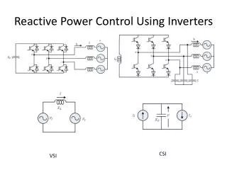
High Power Inverters 1. Application power range of inverter circuits using the basic "inverter leg" building block is now vast (<1kW to 10MW+)

E N D
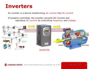
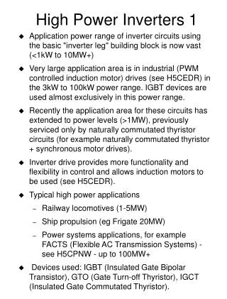
High Power Inverters 1 • Application power range of inverter circuits using the basic "inverter leg" building block is now vast (<1kW to 10MW+) • Very large application area is in industrial (PWM controlled induction motor) drives (see H5CEDR) in the 3kW to 100kW power range. IGBT devices are used almost exclusively in this power range. • Recently the application area for these circuits has extended to power levels (>1MW), previously serviced only by naturally commutated thyristor circuits (for example naturally commutated thyristor + synchronous motor drives). • Inverter drive provides more functionality and flexibility in control and allows induction motors to be used (see H5CEDR). • Typical high power applications • Railway locomotives (1-5MW) • Ship propulsion (eg Frigate 20MW) • Power systems applications, for example FACTS (Flexible AC Transmission Systems) - see H5CPNW - up to 100MW+ • Devices used: IGBT (Insulated Gate Bipolar Transistor), GTO (Gate Turn-off Thyristor), IGCT (Insulated Gate Commutated Thyristor).
High Power Inverters 2 • Design of high power converters (MW range) presents problems • Single devices can’t handle the V and I. • For example a 1MW drive would be typically supplied at 3.3kV (UK) or 4.16kV (US) giving a DC link of 5 to 7kV. The voltage supplied to the motor is also 3.3kV (or 4.16kV). • Device voltage rating required 8-10kV - not available. • Handling high currents by putting devices (or converters) in parallel is fairly well established. Getting the voltage handling capability remains the problem. • Possible solutions are • Use standard converter topologies with devices in series. • Use alternative topology converters which a number of low voltage devices and that have some means for distributing the voltage stress amongst those devices (Multi-level converters).
Series Devices 1 One switch - all devices switched together (N/2)*(E/2) DC supply A O VAO is 2-level (N/2)*(E/2) Total number of devices = N per leg One inverter leg • Assuming that each device is capable of operating at voltage E, then theoretically by using N devices in series we can operate with a DC voltage of (N/2)*E
Series Devices 2 • Problems • The entire DC voltage appears across each switch when it is off. This will be greater than the voltage rating of the individual devices. • The devices will not automatically share the voltage in the off state because of differences in leakage current - high value parallel resistors can be used to overcome this (static sharing). • More seriously, the devices will not share the voltage during switching due to variations in switching speed. Special gate drive techniques and/or special snubbers are required (dynamic sharing). Not well established yet. • Two level output causes very large voltage steps on the load - can be a problem for motor insulation (for example) • Harmonic content (distortion) is larger for a given switching frequency than with multi-level techniques (see later)
Series Devices 3 • Advantages • Standard PWM techniques can be used. • Number of power circuit components is less than with other (multi-level) circuits. • Redundancy can be incorporated (to improve reliability) by using more series devices than actually required - the circuit can then still work if one fails (provided it fails short circuit).
Multi-level Converters 1 • As the name suggests, these circuits produce a waveform with more levels than a standard (2-level) inverter leg Example of 3-level line to line waveform produced by an inverter with standard 2-level inverter legs Example of 5-level line to line waveform produced by an inverter with individual legs that can produce 3-levels
Multi-level Converters 2 • Multi-level converters produce a better output spectrum than 2-level converters employing the same device switching frequency. PWM generation is more complex Comparison of spectra for conventional (3-level) line to line waveform and 5-level line to line waveform • The are 3 basic types of multi-level converter • Isolated H-bridge • Diode clamped converter • Flying capacitor converter
Isolating Trafo E 'H-Bridge' Cell Isolated H-bridge 1 O 1a 2a 3a 1b 2b 3b C A B Output • Each H-bridge must have an isolated DC supply - usually derived from an isolated AC supply via a diode bridge • Each bridge can produce +E, 0, -E independently • With K bridges per phase, VAO etc has 2K+1 levels and VAB has 4K+1 levels • Circuit above has 5-levels in VAO and 9-levels in VAB
Isolated H-bridge 2 • Problems • Each H-bridge needs an isolated DC supply compared to the other solutions which need only one supply. Normally this requires some sort of complicated transformer arrangement. Also the capacitors associated with each supply can be large. • Advantages • Device voltage sharing is automatic because of the independent DC supplies. There is no restriction on switching pattern. • With N devices (each capable of operating at voltage E) per-phase, the circuit can produce an output varying between ±(N/2)*(E/2). This is the same as the series device solution. The advantage is that the output has more levels, giving smaller voltage steps to the load and less harmonic distortion (for a given switching frequency). • Some redundancy is possible by using more H-bridges per phase than is actually required. • By using a lot of H-bridges, very high voltage converters can be made this way. • The circuit is modular – the is an advantage for manufacture and maintenance.
A E B O X A E B OFF E ON O X ON E OFF Diode Clamped Circuit 1 3-level diode clamped circuit (neutral point clamped circuit) One inverter leg shown DC Supply A=1, B=1 VXO = +E A=0, B=1 VXO = 0 A=0, B=0 VXO = -E DC Supply Example current paths for VXO = 0 state
Diode Clamped Circuit 2 Complete 3-phase inverter with 3-level diode clamped legs Popular solution for 500kW – few MW motor drives E DC Supply O O O E B C A VAO etc are 3-level (+E,0,-E) VAB etc are 5-level (+2E, +E, 0, -E, -2E)
Diode Clamped Circuit 3 ABCD=1111 VXO = +2E ABCD=0111 VXO = +E ABCD=0011 VXO = 0 ABCD=0001 VXO = -E ABCD=0000 VXO = -2E DC Supply D1 O X D2 Note: D1 has to block 3E when ABCD=1111 D2 has to block 3E when ABCD=0000 5-level diode clamped circuit One inverter leg shown
Diode Clamped Circuit 4 • Problems • Except in the 3-level circuit, the capacitor voltages do not share automatically. Either some form of extra balancing circuit is needed or multiple (non-isolated) DC supplies are required (one for each capacitor). • As the number of levels increases, some diodes have to block large voltages (see D1 and D2 in previous slide) – makes the circuit unattractive for more than 5-levels since many diodes in series are required (currently). • Difficult to build in redundancy.
Diode Clamped Circuit 5 • Advantages • Only one isolated DC supply is required. • By operating the circuit such that the output from each leg changes one level at a time, the problem of device voltage sharing during transients (dynamic sharing) is avoided. This however makes the switching pattern more restricted than the isolated H-bridge solution. Note: static voltage sharing is not guaranteed without parallel resistors (see earlier notes). • With the same number of devices (ignoring clamp diodes) of equal voltage rating, the circuit can produce the same output voltage levels as the isolated H-bridge solution and operate with the same DC link voltage as the series switch solution.
X A E DC Supply B E O E A B Flying Capacitor Circuit 1 3-level flying capacitor circuit One inverter leg A=1, B=1 VXO = +E A=0, B=1 VXO = 0 A=1, B=0 VXO = 0 A=0, B=0 VXO = -E “Flying” capacitor • Flying capacitor must be pre-charged to E. • Note the difference between the A=0, B=1 and A=1, B=0 states. The voltage produced is the same in both cases, but the current path through the flying capacitor is reversed – this provides the means to keep the capacitor charged to the correct voltage during circuit operation.
E DC Supply E E E O E C B A Flying Capacitor Circuit 2 Complete 3-phase inverter with 3-level flying capacitor legs VAO etc are 3-level (+E,0,-E) VAB etc are 5-level (+2E, +E, 0, -E, -2E)
Flying Capacitor Circuit 3 ABCD VXO 1111 +2E 1110 +E 1101 1100 0 1011 +E 1010 0 1001 1000 0111 +E 0110 0101 0 0100 0011 0 0010 -E 0001 -E 0000 -2E A 2E B C DC Supply D 3E 2E E X O D C B 2E A 5-level flying capacitor circuit One inverter leg shown • Duplicate states (4 ways to get +E, 4 ways to get -E, 6 ways to get 0) provide the means for keeping the capacitor voltages correct.
Flying Capacitor Circuit 4 • Problems • "Flying" capacitors need to be pre-charged. • Switching strategy must be used to maintain flying capacitors at the correct voltage. This must be done via some form of feedback mechanism. • As the number of levels increases, the number of capacitors required increases rapidly (note that the flying capacitors supporting more than E will generally be made from a number of series connected capacitors). • Difficult to build in redundancy.
Flying Capacitor Circuit 5 • Advantages • Only one isolated DC supply is required. • Device voltage sharing is guaranteed (both static and dynamic) if the flying capacitors are kept charged the correct voltage. • No high voltage silicon devices are required (unlike the diodes in the diode clamped circuit) • With the same number of devices of equal voltage rating, the circuit can produce the same output voltage levels as the isolated H-bridge solution and the diode clamped solution and operate with the same DC link voltage as the series switch solution.
Summary • Power range for inverter circuits is extending upwards all the time. • Improvements in device voltage and current ratings can't keep up. • Series devices or multilevel converter structures are required to get voltage handling capability required. • 3 basic types of multilevel converter • Isolated H-Bridge converter • Diode Clamped converter • Flying Capacitor converter • This is a big growth area for Power Electronics at the moment.