Download
1 / 46
490 likes | 1.08k Vues
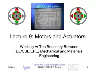
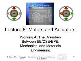
Lecture 8: Motors and Actuators. Working At The Boundary Between EE/CSE/EPE, Mechanical and Materials Engineering. Magnetism. One of the first compasses, a fish shaped iron leaf was mentioned in the Wu Ching Tsung Yao written in 1040 Trinity College, Dublin. Animal Magnetism.

E N D
Lecture 8: Motors and Actuators Working At The Boundary Between EE/CSE/EPE, Mechanical and Materials Engineering Introduction to Engineering Electronics K. A. Connor
Magnetism • One of the first compasses, a fish shaped iron leaf was mentioned in the Wu Ching Tsung Yao written in 1040 Trinity College, Dublin Introduction to Engineering Electronics K. A. Connor
Animal Magnetism • A frog suspended in an intense magnetic field – all of us are paramagnetic • Much money is wasted on magnetic therapy Introduction to Engineering Electronics K. A. Connor
Electromagnetic Revolution • These four equations epitomize the electromagnetic revolution. Richard Feynman claimed that "ten thousand years from now, there can be little doubt that the most significant event of the 19th century will be judged as Maxwell's discovery of the laws of electrodynamics" Introduction to Engineering Electronics K. A. Connor
Magnetic Attraction • It is possible to produce motion using magnetic attraction and/or repulsion • Either permanent magnets or electromagnets or both can be used Introduction to Engineering Electronics K. A. Connor
2 Minute QuizName_____________ Sec___ • True or false, unlike magnetic poles attract and like magnetic poles repel one another. • Name one mechatronic device that you own or use on a regular basis • Which engineering majors are some interest to you? Electrical, Computer & Systems, Electric Power, Nuclear, Mechanical, Aeronautical, Biomedical, Civil, Industrial & Management, Materials, Chemical, Environmental, Engineering Physics Introduction to Engineering Electronics K. A. Connor
Magnetic Attraction and Repulsion • One of the many facts we all recall from our earliest science education Introduction to Engineering Electronics K. A. Connor
DC Motors • The stator is the stationary outside part of a motor. The rotor is the inner part which rotates. In the motor animations, red represents a magnet or winding with a north polarization, while green represents a magnet or winding with a south polariztion. Opposite, red and green, polarities attract. Introduction to Engineering Electronics K. A. Connor
DC Motors • Just as the rotor reaches alignment, the brushes move across the commutator contacts and energize the next winding. In the animation the commutator contacts are brown and the brushes are dark grey. A yellow spark shows when the brushes switch to the next winding. Introduction to Engineering Electronics K. A. Connor
DC Motor Applications • Automobiles • Windshield Wipers • Door locks • Window lifts • Antenna retractor • Seat adjust • Mirror adjust • Anti-lock Braking System • Cordless hand drill • Electric lawnmower • Fans • Toys • Electric toothbrush • Servo Motor Introduction to Engineering Electronics K. A. Connor
Beakman’s Motor • A simple DC motor made with a battery, two paperclips, a rubber band and about 1 meter of enameled wire. Introduction to Engineering Electronics K. A. Connor
Brushless DC Motors • A brushless dc motor has a rotor with permanent magnets and a stator with windings. It is essentially a dc motor turned inside out. The control electronics replace the function of the commutator and energize the proper winding. Introduction to Engineering Electronics K. A. Connor
Brushless DC Motor Applictions • Medical: centrifuges, orthoscopic surgical tools, respirators, dental surgical tools, and organ transport pump systems • Model airplanes, cars, boats, helicopters • Microscopes • Tape drives and winders • Artificial heart Introduction to Engineering Electronics K. A. Connor
Full Stepper Motor • This animation demonstrates the principle for a stepper motor using full step commutation. The rotor of a permanent magnet stepper motor consists of permanent magnets and the stator has two pairs of windings. Just as the rotor aligns with one of the stator poles, the second phase is energized. The two phases alternate on and off and also reverse polarity. There are four steps. One phase lags the other phase by one step. This is equivalent to one forth of an electrical cycle or 90°. Introduction to Engineering Electronics K. A. Connor
Half Stepper Motor • This animation shows the stepping pattern for a half-step stepper motor. The commutation sequence for a half-step stepper motor has eight steps instead of four. The main difference is that the second phase is turned on before the first phase is turned off. Thus, sometimes both phases are energized at the same time. During the half-steps the rotor is held in between the two full-step positions. A half-step motor has twice the resolution of a full step motor. It is very popular for this reason. Introduction to Engineering Electronics K. A. Connor
Stepper Motors • This stepper motor is very simplified. The rotor of a real stepper motor usually has many poles. The animation has only ten poles, however a real stepper motor might have a hundred. These are formed using a single magnet mounted inline with the rotor axis and two pole pieces with many teeth. The teeth are staggered to produce many poles. The stator poles of a real stepper motor also has many teeth. The teeth are arranged so that the two phases are still 90° out of phase. This stepper motor uses permanent magnets. Some stepper motors do not have magnets and instead use the basic principles of a switched reluctance motor. The stator is similar but the rotor is composed of a iron laminates. Introduction to Engineering Electronics K. A. Connor
More on Stepper Motors • Note how the phases are driven so that the rotor takes half steps Introduction to Engineering Electronics K. A. Connor
More on Stepper Motors • Animation shows how coils are energized for full steps Introduction to Engineering Electronics K. A. Connor
More on Stepper Motors • Full step sequence showing how binary numbers can control the motor • Half step sequence of binary control numbers Introduction to Engineering Electronics K. A. Connor
Stepper Motor Applications • Film Drive • Optical Scanner • Printers • ATM Machines • I. V. Pump • Blood Analyzer • FAX Machines • Thermostats Introduction to Engineering Electronics K. A. Connor
Switched Reluctance Motor • A switched reluctance or variable reluctance motor does not contain any permanent magnets. The stator is similar to a brushless dc motor. However, the rotor consists only of iron laminates. The iron rotor is attracted to the energized stator pole. The polarity of the stator pole does not matter. Torque is produced as a result of the attraction between the electromagnet and the iron rotor in the same way a magnet is attracted to a refrigerator door. An electrically quiet motor since it has no brushes. Introduction to Engineering Electronics K. A. Connor
Switched Reluctance Motor Applications • Motor scooters and other electric and hybrid vehicles • Industrial fans, blowers, pumps, mixers, centrifuges, machine tools • Domestic appliances Introduction to Engineering Electronics K. A. Connor
Brushless AC Motor • A brushless ac motor is driven with ac sine wave voltages. The permanent magnet rotor rotates synchronous to the rotating magnetic field. The rotating magnetic field is illustrated using a red and green gradient. An actual simulation of the magnetic field would show a far more complex magnetic field. Introduction to Engineering Electronics K. A. Connor
AC Induction Motor • The stator windings of an ac induction motor are distributed around the stator to produce a roughly sinusoidal distribution. When three phase ac voltages are applied to the stator windings, a rotating magnetic field is produced. The rotor of an induction motor also consists of windings or more often a copper squirrel cage imbedded within iron laminates. Only the iron laminates are shown. An electric current is induced in the rotor bars which also produce a magnetic field. Introduction to Engineering Electronics K. A. Connor
AC Induction Motor • The rotating magnetic field of the stator drags the rotor around. The rotor does not quite keep up with the the rotating magnetic field of the stator. It falls behind or slips as the field rotates. In this animation, for every time the magnetic field rotates, the rotor only makes three fourths of a turn. If you follow one of the bright green or red rotor teeth with the mouse, you will notice it change color as it falls behind the rotating field. The slip has been greatly exaggerated to enable visualization of this concept. A real induction motor only slips a few percent. Introduction to Engineering Electronics K. A. Connor
Aircraft Window Polarizing Drives Antenna Positioning and Tuning Devices Audio/Video Recording Instruments Automated Inspection Equipment Automated Photo Developing Equipment Automated Photo Slide Trimming & Mounting Equipment Automatic Carton Marking & Dating Machines Automatic Dying and Textile Coloring Equipment Automatic Food Processing Equipment Automatic I.V. Dispensing Equipment Automatic Radio Station Identification Equipment Automotive Automotive Engine Pollution Analyzers Baseball Pitching Machine Blood Agitators Blood Cell Analyzer …….. Warning Light Flashers Railroad Signal Equipment Remote Focusing Microscopes Resonator Drives for Vibraphones …….. Silicone Wafer Production Equipment Solar Collector Devices Sonar Range Recorders and Simulators Steel Mill Process Scanners Tape Cleaning Equipment Tape Input for Automatic Typewriters Telescope Drives Ultrasonic Commercial Fish Detectors Ultrasonic Medical Diagnostic Equipment Voltage Regulators Water and Sewage Treatment Controls Weather Data Collection Machines Welding Machines X-Ray Equipment XY Plotters Huge List of Applications from Hurst Introduction to Engineering Electronics K. A. Connor
Stepper Motor from Mechatronics Introduction to Engineering Electronics K. A. Connor
Mechatronics Stepper Motor Continued Introduction to Engineering Electronics K. A. Connor
Mechatronics • Mechatronics is at the intersection between several disciplinary areas, as represented by these Venn diagrams Introduction to Engineering Electronics K. A. Connor
What Is Mechatronics? • Mechatronics is the synergistic integration of mechanical engineering, electronics, controls, and computers; all integrated through the design process. • EXAMPLES: • robots • anti-lock brakes • photocopiers • consumer products (e.g., clothes dryers) • disk drives Introduction to Engineering Electronics K. A. Connor
MEMS • Micro-Electro-Mechanical Systems (MEMS) is the integration of mechanical elements, sensors, actuators, and electronics on a common silicon substrate through the utilization of microfabrication technology. While the electronics are fabricated using integrated circuit (IC) process sequences (e.g., CMOS, Bipolar, or BICMOS processes), the micromechanical components are fabricated using compatible "micromachining" processes that selectively etch away parts of the silicon wafer or add new structural layers to form the mechanical and electromechanical devices. Introduction to Engineering Electronics K. A. Connor
MEMS Stepper Motor • This motor is very much like the other stepper motors mentioned above, except that it is 2D and very small Introduction to Engineering Electronics K. A. Connor
MEMS • The potential complexity of the MEMS device increases exponentially with the number of unique process features and individual structural layers. Introduction to Engineering Electronics K. A. Connor
MEMS: Steam Engine • Water inside of three compression cylinders is heated by electric current and vaporizes, pushing the piston out. Capillary forces then retract the piston once current is removed. Introduction to Engineering Electronics K. A. Connor
MEMS • Rotary motor • Steam Engine (single piston) Introduction to Engineering Electronics K. A. Connor
MEMS Gear Trains • Six gear planar train at various speeds • Close up of six gear train Introduction to Engineering Electronics K. A. Connor
Power MEMS • 80 Watt gas microturbine designed and built at MIT for MEMS power applications Introduction to Engineering Electronics K. A. Connor
Integrated MEMS • This six-degrees-of-freedom micro-inertial measurement system combines microelectronic circuitry [top right] with a couple of • micromechanical elements: an accelerometer [center right] and gyroscope [bottom right]. Introduction to Engineering Electronics K. A. Connor
Integrated MEMS • Types of micromechanical devices that might be used in integrated microsystems of the future [shown clockwise from right] include this gear, pop-up mirror, mirror assembly, and hinge. The gear is part of an assembly that has demonstrated torque ratios of up to 3 million to 1. The silicon mirror is fabricated flat on the silicon wafer, then "popped up" to its raised position using the gear assembly. Introduction to Engineering Electronics K. A. Connor
Integrated MEMS • Sample collection regions for concentration, microseparation channels, sensor arrays for detection, and an exit region are illustrated in schematic of the chemical analysis section of a micro-chemlab. Chemicals are detected measuring the response of surface acoustic-wave devices to a chemical's presence. The photograph is of an array of micromachined 3-µm silicon posts in a microchannel being studied as a tool for enhancing electrokinetically driven liquid separations. Introduction to Engineering Electronics K. A. Connor
MEMS Displays • Iridigm Display -- The iMoD element uses interference to create color in the same way that structural color works in nature. Microscopic structures on butterfly wings and peacock feathers cause light to interfere with itself, creating the shimmering iridescent colors that we see in these creatures. (Used in PDAs) Introduction to Engineering Electronics K. A. Connor
MEMS Displays • The iMoD element is a simple MEMS device that is composed of two conductive plates. One is a thin film stack on a glass substrate, the other is a metallic membrane suspended over it. There is a gap between the two that is filled with air. The iMoD element has two stable states. When no voltage is applied, the plates are separated, and light hitting the substrate is reflected as shown above. When a small voltage is applied, the plates are pulled together by electrostatic attraction and the light is absorbed, turning the element black. Introduction to Engineering Electronics K. A. Connor
MEMS Displays • iMoD elements are minuscule, typically 25-60 microns on a side (400-1,000 dots per inch). Therefore, many iMoD elements are ganged and driven together as a pixel, or sub-pixel in a color display. The color of the iMoD element is determined by the size of the gap between the plates. As shown, the blue iMoD has the smallest gap and the red has the largest. To create a flat panel display, a large array of iMoD elements are fabricated in the desired format (i.e. 5" full color VGA) and packaged. Finally, driver chips are attached at the edge to complete the display. Introduction to Engineering Electronics K. A. Connor
References • Motor Operation Principles from Freescale/Motorola by Ken Berringer • Basic Stepper Motor Concepts • MEMS Clearinghouse • Mechatronics at Rensselaer • Mechatronics.org • Beakman’s Motor: Electronic Instrumentation and Fields and Waves I Introduction to Engineering Electronics K. A. Connor
Primary Course Goal for IEE • Assure that each EE and CSE student has a minimum of 20 hours of practical electronics and instrumentation experience before they begin taking disciplinary courses. • For students with no experience – 20 hours successfully completing labs • For students with some experience – 20 hours completing labs, expanding their knowledge base and helping those with less experience • For students outside of EE and CSE – provide a working knowledge of electronics Introduction to Engineering Electronics K. A. Connor
Where Will You See This Material Again? • Mechatronics: MANE-4490 Mechatronics, MANE-4250 Mechatronic Systems Design, MANE 6960 Sensors & Actuators in Mechatronics • Motor Drives: ECSE/EPOW-4080 Semiconductor Power Electronics and EPOW-4090 Power Electronics Lab • Motor Control: ENGR-2350 Introduction to Embedded Control • Concentration in Power Electronics: EPOW-4080 and MANE-4490 Introduction to Engineering Electronics K. A. Connor