Download
1 / 8
130 likes | 356 Vues
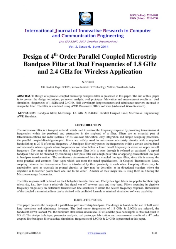
Design of a parallel-coupled microstrip bandpass filter is presented in this paper. The aim of this paper<br>is to present the design technique, parameter analysis, real prototype fabrication and measurement results at dual<br>simulation frequencies of 1.8GHz and 2.4GHz. Half wavelength long resonators and admittance inverters are used to design the filter. The filter is simulated using AWR Microwave Office software (Advanced Wave Research).

E N D
ISSN(Online): 2320-9801 ISSN (Print): 2320-9798 International J ournal of Innovative R esearch in Computer and Communication E ngineering ( An I SO 3297: 2007 Certified Org anization) Vol. 2, Issue 6, J une 2014 Design of 4th Order Parallel Coupled Microstrip Bandpass Filter at Dual Frequencies of 1.8 GHz and 2.4 GHz for Wireless Application S.Srinath UG Student, Dept. Of ECE, Vellore Institute Of Technology, Vellore, Tamilnadu, India ABSTRACT: Design of a parallel-coupled microstrip bandpass filter is presented in this paper. The aim of this paper is to present the design technique, parameter analysis, real prototype fabrication and measurement results at dual simulation frequencies of 1.8GHz and 2.4GHz. Half wavelength long resonators and admittance inverters are used to design the filter. The filter is simulated using AWR Microwave Office software (Advanced Wave Research). KEYWORDS: Bandpass filter; Microstrip; 1.8 GHz & 2.4GHz; Parallel Coupled Line; Microwave Engineering; AWR Simulator. I.INTRODUCTION The microwave filter is a two port network which used to control the frequency response by providing transmission at frequencies within the passband and attenuation in the stopband of a filter. Filters are an essential part of telecommunications and radar systems. Of its low-cost fabrication, easy integration and simple designing procedure, the parallel coupled-line/edge-coupled filters are widely used in microwave microstrip circuits with a required bandwidth up to 20 % of central frequency . A bandpass filter only passes the frequencies within a certain desired band and attenuates others signals whose frequencies are either below a lower cutoff frequency or above an upper cut-off frequency. The range of frequencies that a bandpass filter let’s to pass through is referred as passband. A typical bandpass filter can be obtained by combining a low-pass filter and a high-pass filter or applying conventional low pass to bandpass transformation . The architecture demonstrated here is a coupled line type filter, since this is among the most practical and common filter types which can meet the stated specifications. In Coupled Transmission Lines, coupling between two transmission lines is introduced by their proximity to each other. Coupling effects may be undesirable, such as crosstalk in printed circuits, or they may be desirable, as in directional couplers where the objective is to transfer power from one line to the other . Another of their major use is using them in filtering the Microwave range frequencies. The filter response will be based on the Chebychev transfer function. Chebychev type filters are popular for their high selectivity, i.e., they have a relatively fast signal cut off between pass and stop band. Filters operating in gigaherz frequency ranges rely on distributed transmission line structures to obtain the desired frequency response. Dimensions of the coupled transmission lines can be derived with published formula or minimal simulation software capability. II.RELATED WORK This paper presents the design of a parallel-coupled microstrip bandpass. The design is based on the use of half wave long resonators and admittance inverters. The dual center frequencies of 1.8 GHz & 2.4GHz are selected, the bandwidth (BW) is about 5%, the minimum attenuation amounts to -30 dB and the pass-band ripple is obtained equal to 0.5 dB.The design technique, parameter analysis, real prototype fabrication and measurement results of a 4th order coupled line bandpass filter at a dual simulation frequencies of 1.8GHz & 2.4GHz is presented in this paper. Copyright to IJIRCCE www.ijircce.com 4744
ISSN(Online): 2320-9801 ISSN (Print): 2320-9798 International J ournal of Innovative R esearch in Computer and Communication E ngineering ( An I SO 3297: 2007 Certified Org anization) Vol. 2, Issue 6, J une 2014 III.THEORY A general layout of a parallel coupled microstrip bandpass is shown in figure 3.1 . The filter structure consists of open circuited coupled microstrip lines . These coupled lines are quarter wavelength , (λ/4) long and are equivalent to shunt resonant circuits. The coupling gaps correspond to the admittance inverters in the low-pass prototype circuit. Even- and odd- mode characteristic impedances of parallel-coupled half-wave resonators are computed using admittance inverters. These even- and odd- mode impedances are then used to compute physical dimensions of the filter. Now consider a bandpass filter composed of a cascade of N + 1 coupled line sections, as shown in Figure 3.1. The sections are numbered from left to right, with the load on the right, but the filter can be reversed without affecting the response. Since each coupled line section has an equivalent circuit of the form, the equivalent circuit of the cascade is as shown in Figure 3.2. Figure 3.1 : Layout of an (N + 1)-section coupled line bandpass filter. Figure 3.2 : Using the equivalent circuit of Figure 3.1 for each coupled line section. Copyright to IJIRCCE www.ijircce.com 4745
ISSN(Online): 2320-9801 ISSN (Print): 2320-9798 International J ournal of Innovative R esearch in Computer and Communication E ngineering ( An I SO 3297: 2007 Certified Org anization) Vol. 2, Issue 6, J une 2014 IV. IMMITANCE INVERTER Immittance inverters play a very important role in filterdesign. They are used to transform a filter circuit intoan equivalent form that can be easily implemented usingvarious microwave structures. Immittance inverters are either impedance or admittance inverters. Making use of the properties of immittance inverters, bandpass filters may be realized by series (L-C) resonant circuits separated by impedance inverters (K) or shunt (L-C) parallel resonant circuits separated by admittance inverters (J). To design a bandpass filter, first of all a low-pass prototype circuit is modified to include immittance inverters. These low pass structures are then converted to bandpass circuits by applying conventional low-pass to bandpass transformation. Figure 4.1 : Equivalent circuit of the admittance inverters. V.SIMULATION MODELING AND DISCUSSION The design equations for the coupled line are as follows: The order of the filter was calculated assuming an equi-ripple (Chebyshev type 1) response with an insertion loss (L) of 30dB at the center frequency of 1.8Ghz and 2.4Ghz and the passband ripple amplitude (G) of 0.5dB. The fractional bandwidth Δ = 5%. Hence the upper and lower cutoff frequencies of the passband are 2.52 GHz and 2.28 GHz respectively. Using the standard Chebyshev model: ? ? ??− 1) ???ℎ???(10 ??− 1)/(10 ???ℎ??(? ? = ??) This gives us ? = 4. Now, we get the lowpass prototype values from the standard Chebyshev table: ??= 1 ??= 1.6704 ??= 2.3662 ??= 0.8419 ??= 1.9841 ??= 1.6704 Now, we use the following design equations to get the inverter constants for a coupled line filter with N+ 1 sections: ????= √ΠΔ ?2?? ΠΔ ????= ???????? ; ? = 2,3,4….? Copyright to IJIRCCE www.ijircce.com 4746
ISSN(Online): 2320-9801 ISSN (Print): 2320-9798 International J ournal of Innovative R esearch in Computer and Communication E ngineering ( An I SO 3297: 2007 Certified Org anization) Vol. 2, Issue 6, J une 2014 ΔΠ ??????= ? ??????? Using these equations, we get: ????= 0.2168 ????= 0.0556 ????= 0.0467 ????= 0.0556 ????= 0.2168 Now, the even and odd mode impedances can be calculated as follows: ???= ??[1 + ???+ (???)?] ???= ??[1+ ???+ (???)?] The results of these calculations are tabulated below: N ???(Ω) ???(Ω) 1 63.191 41.512 2 52.934 47.378 3 52.446 47.778 4 52.936 47.377 5 63.192 41.514 The substrate used is a standard FR4 substrate (MSUB) with ??= 4.4? = 1.58??,? = 0.036?? and ????= 0.005. Using a coupled line calculator, the width, length and line spacing for each coupled line was calculated: Line W(mm) L(mm) S(mm) 1 2.70182 69.11613 0.794745 2 2.98623 68.10692 3.450721 3 3.0021 68.05937 3.948424 4 2.98624 68.10694 3.450725 5 2.70188 69.11616 0.794743 Based on the above values and taking standard port impedances as ??= 50Ω, the design was simulated. Copyright to IJIRCCE www.ijircce.com 4747
ISSN(Online): 2320-9801 ISSN (Print): 2320-9798 International J ournal of Innovative R esearch in Computer and Communication E ngineering ( An I SO 3297: 2007 Certified Org anization) Vol. 2, Issue 6, J une 2014 V.SIMULATION DESIGN, RESULTS & DISCUSSION The design was simulated using AWR Design Environment (9.00.4847) and a response was generated. The coupled line design used for simulation was MCFIL which is a non-floating line. This is a coupled line model with the end effect included for the open ended line. One side of each coupled line is the ground plane. Figure 5.1 : Layout of the proposed 4th order filter design in AWR Software Here, the parameter ???(dB) represents the insertion loss at port 1 and this parameter which has a value of -6.521dB at the center frequency of 2.4 GHz while -6.587dB at the center frequency of 1.8GHz The parameter ??? (dB) represents the insertion loss from port 1 to port 2 which has a value of -2.633dB at the center frequency of 2.4GHz while -6.375dB at the center frequency of 1.8GHz. Figure 5.2 : Coupled Line Bandpass Filter at Dual Frequencies Result The first design discussed above was simulated in AWR.The same was simulated using EM simulation. The schematic diagram for the same is given below: Copyright to IJIRCCE www.ijircce.com 4748
ISSN(Online): 2320-9801 ISSN (Print): 2320-9798 International J ournal of Innovative R esearch in Computer and Communication E ngineering ( An I SO 3297: 2007 Certified Org anization) Vol. 2, Issue 6, J une 2014 Figure 5.3 : Layout of the proposed 4th order filter design in AWR Software using EM simulation Here, the parameter ???(dB) represents the insertion loss at port 1 and the parameter which has a value of -2.606dB at the center frequency of 2.4 and 1.8GHz The parameter ??? (dB) represents the insertion loss from port 1 to port 2 which has a value of -16.87dB at the center frequency of 2.4GHz while -31.55dB at the center frequency of 1.8GHz. Figure 5.4 : Coupled Line Bandpass Filter at Dual Frequencies EM Simulation Result For the Stackup, the dielectric used is FR4 and the conductor is copper. The transmission lines used in the design are MCLIN which are essentially similar to MCFIL lines with their remaining ends left open. The thickness of the dielectric layer is taken as 1.58mm and air thickness is taken as 24mm. The simulation is done on EMSight with X and Y cell resolution of 0.5mm and an extension of 1mm. The extracted EM schematic is given below: Copyright to IJIRCCE www.ijircce.com 4749
ISSN(Online): 2320-9801 ISSN (Print): 2320-9798 International J ournal of Innovative R esearch in Computer and Communication E ngineering ( An I SO 3297: 2007 Certified Org anization) Vol. 2, Issue 6, J une 2014 Figure 5.5 :3D View of the Coupled Line Bandpass Filter Figure 5.6 :3D View of the Extraced EM Strucure VI.CONCLUSION On a substrate with a dielectric constant of 4.4,with the dual center frequencies of 1.8 GHz & 2.4 GHz, a coupled line bandpass filter was simulated with the bandwidth of about 5%, with the minimum attenuation of 30 dB and with the pass-band ripple equal to 0.5 dB. Thus the design technique, parameter analysis, real prototype fabrication and measurement results at dual simulation frequencies of 1.8GHz and 2.4GHz of a 4th order coupled line bandpass filter was presented in this paper. VIII.ACKNOWLEDGEMENT At the outset, I would like to express my gratitude for my institute – Vellore Institute of Technology (V.I.T.) for providing me with the opportunity to undergo my undergraduate training, and assimilate knowledge and experience hitherto unknown to me. Copyright to IJIRCCE www.ijircce.com 4750
ISSN(Online): 2320-9801 ISSN (Print): 2320-9798 International J ournal of Innovative R esearch in Computer and Communication E ngineering ( An I SO 3297: 2007 Certified Org anization) Vol. 2, Issue 6, J une 2014 REFERENCES [1] [2] D. M. Pozar, “Microwave Engineering”, John Wiley & Sons Inc., 1998. Miguel Bacaicoa, David Benito, Maria J. Garde, Mario Sorolla and Marco Guglielmi, “New Microstrip Wiggly-Line Filters with Spurious Pass-band Suppression”, IEEE Transactions on microwave theory and techniques, vol. 49, no. 9, September 2001. John T. Taylor and Qiuting Huang, “CRC Handbook of Electrical Filters”, CRC Press, pp. 22-23, 1997. “Tuning, Optimization and Statistical Design”, Agilent Technologies, May 2003. R. Levy, S. B. Cohn, “A History of Microwave Filter Research, Design, and Development”, Microwave Theory and Techniques, IEEE Transactions, vol. 32, no. 9, pp. 1055,1067, Sep 1984. A. Naghar, O. Aghzout, F. Medina, M. Alaydrus, M. Essaidi, “Study and Design of a Compact Parallel Coupled Microstrip Band-Pass Filter for a 5 GHz Unlicensed Mobile WiMAX Networks,” International Journal of Science and Technology, vol. 2, No. 6, June 2013. Sina Akhtarzard, Thomas R. Rowbotham, and Petter B. Johns, “The Design of Coupled Microstrip Lines”, IEEE Transactions on Microwave Theory and Techniques, vol. MTT-23, no. 6, pp. 486-492, June 1975. E. O. Hammerstard, “Equations for microstrip circuit design,” in Proceedings of the European Microwave Conference, Hamburg, Germany, 1975, pp. 268–272. Annapurna Das and Sisir K Das, “Microwave Engineering”, MacGraw Hill, p305, 2001. Hong, J.S., M.J, “Microstrip Filter for RF/Microwave Applications”, A Wiley- Interscience Publication, Canada, 2001. C. A Balanis, “Antenna Theory: Analysis and Design”, 3rd edition, Wiley, 2005. S. B. Cohn, “Parallel-Coupled Transmission-Line-Resonator Filters,” Microwave Theory and Techniques, IRE Transactions on , vol. 6, no. 2, pp. 223-231, April 1958. [10]S. Seghier, N. Benahmed, F. T. Bendimerad, N. Benabdallah, “Design of parallel coupled microstrip bandpass filter for FM Wireless applications”, Sciences of Electronics, Technologies of Information and Telecommunications (SETIT), 6th International Conference , pp.207- 211, 21-24 March 2012. A. R Othman, I.M. Ibrahim, M. F. M. Selamat, M. S. A. S. Samingan, A. A. A. Aziz, H. C. Halim, “5.75 GHz microstrip bandpass filter for ISM band”, Applied Electromagnetics, APACE Asia-Pacific Conference on , pp. 1-5, 4-6 Dec. 2007. I. Azad, Md. A. H. Bhuiyan, S. M. Y. Mahbub, “Design and Performance Analysis of 2.45 GHz Microwave Bandpass Filter with Reduced Harmonics”, International Journal of Engineering Research and Development, vol. 5, no. 11, pp. 57-67, 2013. [11]John T. Taylor and Qiuting Huang, “CRC Handbook of Electrical Filters”, CRC Press, pp. 22-23, 1997. [3] [4] [5] [6] [7] [8] [9] BIOGRAPHY S.SRINATH passed 10th C.B.S.E. Board with a mark of 475/500(95%) and 12th C.B.S.E. Board from D.A.V. Boys Senior Secondary School,Gopalpuram,Chennai with a mark of 458/500(91.6%).Currently he is studying B.Tech, ECE, School of Electronics Engineering in VIT University,Vellore, India. Copyright to IJIRCCE www.ijircce.com 4751