Download

1 / 4
40 likes | 56 Vues
This paper combines the Internet of things technology with environmental protection and embeds passive RFID in<br>the environmental protection equipment for real-time data acquisition to promote energy saving renovation work.<br>Design passive RFID antenna and simulate the designed antenna. RFID tags need to mount on metallic objects in<br>many practical applications. However, these tags may cannot operate normally because that electromagnetic wave<br>scattering from the metal plane. Output the simulation results of the input impedance and return loss to indicate the<br>design of the antenna is feasible and the advantages of RFID technology in the application.<br>

E N D
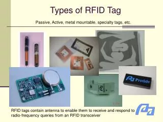
Available online www.jocpr.com Journal of Chemical and Pharmaceutical Research, 2013, 5(9):571-574 ISSN : 0975-7384 CODEN(USA) : JCPRC5 Research Article Based on the passive RFID tag control of sewage treatment equipment Li Jie1, Zhang Lina1 and Wang Weina2 16F, E block, Jiahua building, 9#, 3rd street Shangdi, Haidian District, Beijing, China 28 Guangrongdao, Hongqiao District, Tianjin, China _____________________________________________________________________________________________ ABSTRACT This paper combines the Internet of things technology with environmental protection and embeds passive RFID in the environmental protection equipment for real-time data acquisition to promote energy saving renovation work. Design passive RFID antenna and simulate the designed antenna. RFID tags need to mount on metallic objects in many practical applications. However, these tags may cannot operate normally because that electromagnetic wave scattering from the metal plane. Output the simulation results of the input impedance and return loss to indicate the design of the antenna is feasible and the advantages of RFID technology in the application. Keywords: Internet of things, RFID, Sewage treatment equipment _____________________________________________________________________________________________ INTRODUCTION With the environmental pollution increasing seriously, energy saving is becoming the hot topic. Only by real-time monitoring equipment operation data, can we understand its running state in the first time and embedded passive RFID on the device can solve the above problems. Environmental protection equipment with its unique requirements should be equipped with passive RFID more extensively [1]. Internet of things has generic in the sense, reliable transmission, intelligent processing etc, combined with the requirements of the energy conservation and emissions reduction, which could lead to the common key technology innovation and implementation. Passive RFID embedded in the environmental protection equipment, which can provide data basis for energy saving transformation through real-time acquisition, identification of main energy consumption equipment, targeted energy saving renovation work. The Uniqueness of Environmental Protection Equipment. Environmental protection equipment is different from the ordinary mechanical equipment, which is used to control the environmental pollution, improve environmental quality and the production unit or building installation unit manufacture and construction of mechanical products, structures and systems [2]. Environmental protection equipment running efficiency and smoothly can reduce urban pollution and maintain the normal operation of the society. Under these requirements, the competent departments must be able to get the real-time data to monitor and manage the equipment. Eventually to reach the significance of its existence: protect the environment. RFID TECHNOLOGY Radio frequency identification can identify specific object and read-write relevant data automatically. In this communication technology, identification system needn’t build mechanical or optical contact with the specific object. Recently, RFID system in ultra-high-frequency (UHF: 860-960 MHz) band has attract much attention and grows rapidly because of its long reading distance. RFID tags need to mount on metallic objects in many practical applications. However, these tags may cannot operate normally because that electromagnetic wave scattering from the metal plane. Many researchers have present several tag antenna for metal surface. But they can not meet 571
Li Jie et al ______________________________________________________________________________ J. Chem. Pharm. Res., 2013, 5(9):571-574 production cost requirement. So designation of high performance-price ratio tag antenna is needed in the application of a tag mounted on metal. In this paper, we present a flexible, wideband antenna for tag that mounted inside metallic groove. Dipole antenna: Dipole antenna can transmit and receive the fixed frequency signals. In the usual measurement using the broadband antenna, but in the attenuation coefficient and antenna measurement field, the dipole antenna is used. SCHWARZBECK dipole antenna in the frequency range of 30 MHZ ~ 4 GHZ. VHAP and UHAP is a set of precise dipole antenna, especially suitable for field attenuation coefficient and antenna measurement [3]. The antenna is adopted by many laboratories, as a standard laboratory antenna. Vertical antenna is actually a dipole antenna. Dipole antenna is composed of two conductors, each for a quarter wavelength, namely the total length of half wave antenna. So call half wave dipole as antenna vibrator. Dipole antenna vibrator can be horizontal or vertical position. The direction of the figure is symmetrical to feed point that in the center of the half wave oscillator. Feed point impedance is pure resistance, approximately 75 Ω (about 73 Ω) [4]. If extended the two 1/4 wavelength of vibrator returning to center and connect together, it became a folded dipole antenna, namely folding oscillator. Folded dipole antenna impedance is purely resistive approximate 300 Ω (about 290 Ω), showing a high input impedance, which is used in many occasions with high impedance transmission antenna composed of parallel feeder. Antenna structure: In finished production, the material of antenna is copper and the antenna with impinj’s Monza-4 chip is placed on 3.5 mm epoxy FR-4 substrate. In simulation, the parameters of the tag can be equivalent that relative permittivity=4.4 and thickness=3.5 mm [5]. We analyze the tag performance by compared with simulation and measurement result. The geometry of the proposed antenna is shown in Fig. 1. The length of the proposed antenna is 84 mm, the width is 6 mm, the height is 0.05 mm and the line wide is 0.75 mm. A prominent difference with other applications is that the designed tag is embedded in the metallic groove and more electromagnetic disturbances maybe appear. ANTENNA DESIGN Two prototype antennas were designed using Ansoft HFSS. Fig. 1 and Fig. 2 show the detailed dimension of the designed antenna. The antenna impedance is matched to the impedance of impinj’s Monza-4 chip at around 840 MHz. Fig. 1 The first geometric shape of the first designed antenna (Unit: mm) Fig. 2 The second geometric shape of the second designed antenna (Unit: mm) THE RFID TEST AND RESULTS The Monza-4 chip has an approximate impedance of Zc = (13-j151) Ω at 840 MHz. At 840 MHz, the value of the first antenna simulation result is Zc = (7.05+j151.26) Ω and the second antenna simulation result is Zc = (11.98+j407.82) Ω. Fig. 3 and Fig. 5 show the plots of the simulated antenna impedances against frequency respectively, which agree well with each other. Fig. 4 and Fig. 6 show the simulated return losses (RLs) of the antenna respectively, with respect to Zc. 572
Li Jie et al ______________________________________________________________________________ J. Chem. Pharm. Res., 2013, 5(9):571-574 250 200 150 Input impedance() 100 Imaginary Part Real Part 50 0 -50 -100 -150 700 720 740 760 780 Frequency(MHz) 800 820 840 860 880 900 Fig. 3 The first simulated input impedance 20 10 0 Return loss(dB) -10 -20 -30 -40 700 720 740 760 780 Frequency(MHz) 800 820 840 860 880 900 Fig. 4 The first simulated return loss 700 600 500 Input impedance() 400 300 Imaginary Part Real Part 200 100 0 700 720 740 760 780 Frequency(MHz) 800 820 840 860 880 900 Fig. 5 The second simulated input impedance 573
Li Jie et al ______________________________________________________________________________ J. Chem. Pharm. Res., 2013, 5(9):571-574 -4 -6 -8 -10 Return loss(dB) -12 -14 -16 -18 -20 700 720 740 760 780 Frequency(MHz) 800 820 840 860 880 900 Fig. 6 The second simulated return loss CONCLUSION As shown in figures above, the error of simulation results is very small. So we present two wideband, flexible antennas for RFID tags that mounted inside metallic groove. The tag consists of the designed antenna, impinj’s Monza-4 chip and the flexible FR-4 substrate, which satisfies the demand. No matter from the input impedance contrast or return loss of contrast, both performance is perfect. But considering all aspects, the second antenna design is more accurately. So, add the RFID to the environmental protection equipment is desirable REFERENCES [1]Sun XG, Zhang C, Li YM. China Integrated Circuit. 2007(1):29-35. [2]Tan GY, Huang YL, Wang ZB. Specialist Forum. 2010(10):51-53. [3]Yang YS, Wu YS, Xiong LZ. Modern Electronics Technique. 2011(34):182-184. [4]Wu YS. Forefront of RFID. 2008(4):48-52. [5]Wang HG, Pei CX, Yi YH. Chinese Journal of Computers. 2009(32):1356-1362. 574