Download

1 / 39
430 likes | 1.46k Vues
RFID Passive Tag Architecture. Shariful Hasan Shaikot Graduate Student shaikotweb@yahoo.com Oklahoma State University. Outline. What is RFID tag RFID System Classification of RFID tag Passive Tag What it is? Main Concern Physical Implementation What passive tag must do?

E N D
RFID Passive Tag Architecture Shariful Hasan Shaikot Graduate Student shaikotweb@yahoo.comOklahoma State University
Outline • What is RFID tag • RFID System • Classification of RFID tag • Passive Tag • What it is? • Main Concern • Physical Implementation • What passive tag must do? • How communication occurs? • Description of Different blocks of Passive Tag • Antenna • Demodulator • Modulator • Power generator • Control Unit • Clock frequency block • Collision Detection • Line Coding • Conclusion • References
What is RFID Tag • A radio frequency tag (transponder) is an integrated circuit containing – • the RF circuitry and • the antenna
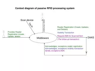
RFID System • A basic RFID system consists of – • a radio frequency tag (transponder) and • a reader (interrogator) • The reader sends out the RF signal carrying commands to the tag. • Consequently, the tag responds with its stored data to be authorized, detected, or counted.
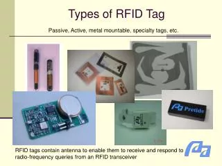
Classification of RFID Tag • Three types of tag • Active tag • Semi Passive Tag • Passive Tag • Another classification of tag • read-write (R/W) - have an additional high voltage charge pump circuitry that provides a higher power supply required for the write operation in the memory cell • read-only (R/O) - animal identification, access control and industrial automation
Passive Tags • Passive tags have no • On-tag power source - they make use of the power received from the incoming RF signal to generate their own supply voltage • On-tag transmitter • Passive tags have ranges of less than 10 meters • Low cost
Passive Tags • Main concern • Power consumption – relies on electromagnetic fields for power, energy is limited • Size – directly affects cost; the more silicon is used, the more expensive the chip; Reducing the number of components will minimize cost but causes high power consumption, TRADEOFF!!! • Cost
Physical implementation of Tag • A tag consists of an antenna attached to an electronic circuit • The antenna acts as a transducer between electromagnetic fields and electric energy . • A transmission line transfer this energy to circuitry and vice versa • The circuitry processes this energy, stores it, uses it and redirects it back through the transmission line and antenna
Physical implementation of Tag • The RF front end is responsible for bidirectional interfacing between the antenna and other functional blocks of the tag • In the RF front end, energy and data are extracted from the input signal and sent to power supply, clock recovery and data processing circuitry • Over voltage protection is located in the front end • The type of memory used is Read Only Memory (ROM) or Write Once Read Many (WORM)
What Passive Tags must do? • Passive tags must receive and rectify the incoming signal for the extraction of energy and information • It must store and manage the extracted energy to power the tag • From the extracted information it must establish a clocking signal with which to drive its digital circuitry • Through this circuitry, it must process the information and make the appropriate modulations of the incoming signal through backscatter modulation
How communication occurs? • Data between reader and tag are transmitted in half-duplex mode. • The reader continuously generates a RF carrier wave, which powers a passive tag when the tag is within its read range. • The tag provides an acknowledgement to the reader by backscatter and the detected modulation of the field indicates the presence of the tag. • The time taken for the tag to become fully functional is called the setup time. After this time, the reader requests for read/write access by sending appropriate instructions to the tag.
How communication occurs? (Contd…) • The demodulator recovers the input data stream and passes control logic circuitry deciphers the data to take corresponding action. • After demodulation of the received instructions and handshaking, the information stored in the tag is transmitted back to the reader by backscattering. • After all of the read/write operations are completed, the reader acknowledges the successful completion of the communication and the tag shuts off.
Antenna system • Passive RFID tags are powered by the microwave signal received by the antenna • The tag needs a minimum signal level at its antenna terminals to operate properly • The tag will absorb some of the power to powering up itself and detecting information • It will scatter some power to transmit information back to the reader
Data Demodulation • In the case of passive operation, there is a strict power constraint on the tag’s design • BER might be sacrificed for the simplicity of design and power reduction in choosing the modulation scheme of the RFID system. • In most of the passive RFID applications the data rate required is relatively low • Bandwidth efficiency may be traded for simplicity in a passive RFID system • Binary signaling should be preferred over M-ARY schemes.
Data Demodulation (contd…) • Digital modulation schemes are preferred over the analog schemes as they have better noise immunity and compatibility with the developing technology of DSPs • The information (from reader to tag) is conveyed through changes in amplitude (ASK), phase (PSK) or frequency (FSK) of the carrier signal. • Another technique is Pulse Width Modulation (PWM) in which the information is conveyed through variations of the width of pulse. • The demodulation schemes are ASK, FSK, PSK and PWM.
Description of Demodulator • a preamplifier is used before the envelope detector to provide a DC level shift to the input signal and perform amplification for better detection. • The envelope detector eliminates the carrier signal from the received signal and provides the baseband modulating signals • Due to the non-idealities (i.e. ripples and peak clipping effects) at the output of the envelope detector, a Schmitt Trigger is used to recover the clear digital pulse train. • The output of the Schmitt Trigger serves as the clock at the data rate for the rest of the processing circuitry • The generated system clock is used to control the operation of the integrator and sample the output of comparator properly.
Modulation • Passive tags do not have enough power to generate a carrier and modulate it, or to have a transmitter circuit. • RFID applications use the Backscatter Modulation technique whether it is ASK or PSK in transferring data from the tag (transponder) to the reader (interrogator)
Backscatter modulation • In the far-field, variation of the tag’s load impedance causes an intended mismatch in impedance between the tag’s antenna and load. This causes some power to be reflected back through the antenna and scattered, much like the antenna is radiating its own signal. The return scattered signal is detected and decoded by the reader.
Backscatter communication between a passive tag and the reader
Power generation block • The reader continuously generates a RF carrier wave, which powers a passive tag when the tag is within its read range. • It makes use of RF-DC conversion and subsequent voltage regulation to obtain the desired stable power supply. • An enable signal is used to indicate the successful generation of the power supply (VDD). • A significant design challenge for the PG block is to maintain a stable supply voltage
Power generation block • The resonator/matching network is connected between the antenna and the rectifier; and provides frequency selectivity and voltage gain to the system. • The significant voltage gain enables the rectifier to overcome its dead zone limitations. • The intrinsic physical limitation on the operation of the devices (e.g. the cut-in voltage of the diodes) is called the dead zone of the device. • The charge pump is used to boost the DC signal generated at the output of the rectifier • The charge stored across the load capacitor of the charge pump (Cload) provides the unregulated supply voltage after the setup time.
Power generation block • The reference circuit aims at generation of an independent reference voltage to be used in voltage regulation • The regulator is used to regulate the output of the charge pump and provide a stable power supply (VDD) to the rest of the chip. It minimizes the ripples and improves immunity to load variations • The charge stored across the load capacitor of the charge pump (Cload) provides the unregulated supply voltage after the setup time.
Control Unit block • The instruction format is represented by 12b: • 4b opcode • 4b destination register address • 4b source register address • The instruction set has 29 operations including an immediate addressing mode
Control Unit block • Registers in the CPU are organized as: • A Program counter • An Immediate register • An I/O register • 13 general purpose registers • The demodulated data from RF block and modulation data from the CPU are transferred through the I/O register • Data transfer between memory (ROM/EEPROM) and register is operated by LOAD/STORE instructions, in which the memory address field refers to a register
Clock Frequency Control Circuit • The clocking signal is used to drive the digital circuitry of passive RFID tags • In the data transmission, the lower frequency clock is selected since fewer CPU executions are required
Line Coding • For digital data transport line coding is often used. • Line coding consists of representing the digital signal to be transported, by an amplitude- and time-discrete signal, that is optimally tuned for the specific properties of the physical channel (and of the receiving equipment). • The waveform pattern of voltage or current used to represent the 1s and 0s of a digital signal on a transmission link is called line encoding. • NRZ, Manchester, RZ, Miller, PWM
Collision Detection • Anti-collision methods require the ability to detect collision • Collision detection relies on coding scheme • When simultaneously transmitted signals coded by certain schemes add, they can not be resolved • Manchester and other transition codes inherently allow this means of collision detection • NRZ and related level codes DO NOT allow this means of collision detection
Collision Detection • Other methods rely on modulation schemes • Through FSK modulation in tag to reader transmission, readers can detect “woobles” when multiple tag responds simultaneously
Conclusion • Passive RFID tags can work on different frequency bands, ranging from kHz to GHz. • The choice of the frequency of operation affects the overall design of the tag, since it controls the complexity, the cost, and the range of operation
References • Faisal A. Hussien, Didem Z. Turker, Rangakrishnan Srinivasan, Mohamed S. Mobarak, Fernando P. Cortes and Edgar Sánchez-Sinencio, “Design considerations and tradeoffs for passive RFID tags”, VLSI Circuits and Systems II, Rosa, Proceedings of SPIE Vol. 5837, (SPIE, Bellingham, WA, 2005) • S. Masui, E. Ishii, T. Iwawaki, Y. Sugawara, K. Sawada, “A 13.56MHz CMOS RF Identification Transponder Integrated Circuit With A Dedicated CPU”, IEEE International Solid-State Circuits Conference, Digest of Technical Papers, Page:162 – 163, Feb. 1999.
The End THANK YOU