Download
1 / 7
80 likes | 262 Vues
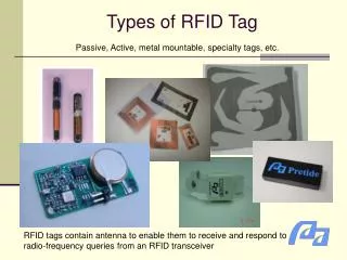
RFID Tag Antennas as Scatterers Preliminary Report. Daniel M. Dobkin March 2005. Experimental Configuration. MPR6000 + nominal 8 dBi vertically polarized panel antenna; 27 dBm nominal output power, 0 nominal delay (about 10% duty cycle), class 1 only

E N D
RFID Tag Antennas as ScatterersPreliminary Report Daniel M. Dobkin March 2005
Experimental Configuration • MPR6000 + nominal 8 dBi vertically polarized panel antenna; 27 dBm nominal output power, 0 nominal delay (about 10% duty cycle), class 1 only • Alien ‘I’ tags on foam board (configuration varied) • Agilent 4417 A power meter in peak-reading mode • Each data point = 20-30 seconds to capture best peak
First set: 9 tags on board • Board configuration: • Result: • That is: • Horizontally oriented tags have little effect on vertically-polarized impinging radiation • Vertically polarized tags reduce received signal by about 8 dB at 10-15 cm distance
Second set: 18 tags on board • Board configuration: • Result: • That is: • Adding more tags leads to slightly increased received signal • Note we are sitting in the ‘bright spot’ centered behind the obstacle…
Lateral slice • Check signal distribution behind obstacle: • Slightly higher attenuation but no sign of a ‘bright spot’ around the center • Remember we’re hopping and selecting for best signal; optimal scattering configuration accidentally encountered in each case?
In-plane obstacle • Reorient TX and RX antennas for horizontal polarization • Interpose board with 6 rows of tags laid out horizontally, varying relative height
In-plane obstacle: results • Strong attenuation in plane of tags • as much as 22 dB • Attenuation extends out of plane of tags • Receiver remains in shadow even when obstructing tags are 15 cm above it • Apparent shadow edge is sharp! 18 dB in 5 cm • Sloppy experimental procedure: why is unobstructed signal 13 dB higher than before? • I didn’t record any change in distance • Horizontal polarization – floor bounce? If so, must be folded into results…repeat with vertical polarization?