Download
1 / 32
460 likes | 2.02k Vues
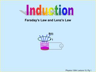
~. Induction. B(t). Faraday’s Law and Lenz’s Law. i. Overview of Lecture. Induction Effects Faraday’s Law (Lenz’ Law) Energy Conservation with induced currents? Faraday’s Law in terms of Electric Fields. Text Reference: Chapter 31.1-4. S. N. N. S. N. S. S. N. v. v. v.

E N D
~ Induction B(t) Faraday’s Law and Lenz’s Law i
Overview of Lecture • Induction Effects • Faraday’s Law (Lenz’ Law) • Energy Conservation with induced currents? • Faraday’s Law in terms of Electric Fields Text Reference: Chapter 31.1-4
S N N S N S S N v v v Induction Effects • Bar magnet moves through coil Þ Current induced in coil • Change pole that enters Þ Induced current changes sign • Bar magnet stationary inside coil Þ No current induced in coil • Coil moves past fixed bar magnet Þ Current induced in coil
a b Induction Effectsfrom Currents • Switch closed (or opened) • Þ current induced in coil b • Steady state current in coila • Þno current induced in coilb • Conclusion: A current is induced in a loop when: • there is a change in magnetic field through it • loop moves through a magnetic field • How can we quantify this? Demo
dS B B Faraday's Law • Define the flux of the magnetic field through a surface (closed or open) from: • Faraday's Law: The emf induced in a circuit is determined by the time rate of change of the magnetic flux through that circuit. • The minus sign indicates direction of induced current (given by Lenz's Law).
S N N S B B v v • Lenz's Law: • The induced current will appear in such a direction that it opposes the change in flux that produced it. Lenz's Law • Conservation of energy considerations: Claim: Direction of induced current must be so as to oppose the change; otherwise conservation of energy would be violated. • Why??? • Ifcurrent reinforced the change, then the change would get bigger and that would in turn induce a larger current which would increase the change, etc..
y 1A x (a) ccw (b) cw (c) no induced current y 1B x (a) ccw (b) cw (c) no induced current Lecture 18, CQ • A conducting rectangular loop moves with constant velocity v in the +x direction through a region of constant magnetic field B in the -z direction as shown. • What is the direction of the induced current in the loop? • A conducting rectangular loop moves with constant velocity v in the -y direction and a constant current I flows in the +x direction as shown. • What is the direction of the induced current in the loop?
y 1A x (a) ccw (b) cw Lecture 16, ACT 1 • A conducting rectangular loop moves with constant velocity v in the +x direction through a region of constant magnetic field B in the -z direction as shown. • What is the direction of the induced current in the loop? (c) no induced current • There is a non-zero flux FB passing through the loop since B is perpendicular to the area of the loop. • Since the velocity of the loop and the magnetic field are CONSTANT, however, this flux DOES NOT CHANGE IN TIME. • Therefore, there is NO emf induced in the loop; NO current will flow!!
i y Lecture 16, ACT 1 • A conducting rectangular loop moves with constant velocity v in the +x direction through a region of constant magnetic field B in the -z direction as shown. • What is the direction of the induced current in the loop? x (a) ccw (b) cw (c) no induced current y • A conducting rectangular loop moves with constant velocity v in the -ydirection and a constant current I flows in the +x direction as shown. • What is the direction of the induced current in the loop? x (a) ccw (b) cw (c) no induced current • The flux through this loop DOES change in time since the loop is moving from a region of higher magnetic field to a region of lower field. • Therefore, by Lenz’ Law, an emf will be induced which will oppose the change of flux. • The current i is induced in the clockwise direction to restore the flux.
v ~ side view B F · · B · F B top view DemoE-M Cannon • Connect solenoid to a source of alternating voltage. • The flux through the area ^ to axis of solenoid therefore changes in time. • A conducting ring placed on top of the solenoid will have a current induced in it opposing this change. • There will then be a force on the ring since it contains a current which is circulating in the presence of a magnetic field.
Ring 1 (c) F2 > F1 (b) F2 = F1 (a) F2 < F1 Ring 2 (c) F2 > F1 (b) F2 = F1 (a) F2 < F1 Lecture 18, CQ • Let us predict the results of variants of the electromagnetic cannon demo which you just observed. • Suppose two aluminum rings are used in the demo; Ring 2 is identical to Ring 1 except that it has a small slit as shown. Let F1 be the force on Ring 1; F2 be the force on Ring 2. • Suppose two identically shaped rings are used in the demo. Ring 1 is made of copper (resistivity = 1.7X10⁻⁸W-m); Ring 2 is made of aluminum (resistivity = 2.8X10⁻⁸W-m). Let F1 be the force on Ring 1; F2 be the force on Ring 2.
Ring 1 Ring 2 Lecture 18, CQ • For this ACT, we will predict the results of variants of the electromagnetic cannon demo which you just observed. • Suppose two aluminum rings are used in the demo; Ring 2 is identical to Ring 1 except that it has a small slit as shown. Let F1 be the force on Ring 1; F2 be the force on Ring 2. (c) F2 > F1 (b) F2 = F1 (a) F2 < F1 • The key here is to realize exactly how the force on the ring is produced. • A force is exerted on the ring because a current is flowing in the ring and the ring is located in a magnetic field with a component perpendicular to the current. • An emf is induced in Ring 2 equal to that of Ring 1, but NO CURRENT is induced in Ring 2 because of the slit! • Therefore, there is NO force on Ring 2!
Ring 1 Ring 2 Lecture 18, CQ • For this ACT, we will predict the results of variants of the electromagnetic cannon demo which you just observed. • Suppose two aluminum rings are used in the demo; Ring 2 is identical to Ring 1 except that it has a small slit as shown. Let F1 be the force on Ring 1; F2 be the force on Ring 2. (c) F2 > F1 (b) F2 = F1 (a) F2 < F1 • Suppose two identically shaped rings are used in the demo. Ring 1 is made of copper (resistivity = 1.7X10⁻⁸W-m); Ring 2 is made of aluminum (resistivity = 2.8X10⁻⁸W-m). Let F1 be the force on Ring 1; F2 be the force on Ring 2. (c) F2 > F1 (b) F2 = F1 (a) F2 < F1 • The emf’s induced in each ring are equal. • The currents induced in each ring are NOT equal because of the different resistivities. • The copper ring will have a larger current induced (smaller resistance) and therefore will experience a larger force (F proportional to current).
x x x x x x x x x x x x x x x x x x x x x x x x I w v x Calculation • Suppose we pull with velocity v a coil of resistance R through a region of constant magnetic field B. • What will be the induced current? • What direction? • Lenz’ Law Þ clockwise!! • What is the magnitude? • Magnetic Flux: • Faraday’s Law: Þ \
The induced current gives rise to a net magnetic force ( ) on the loop which opposes the motion. ' F F F ' F • Agent must exert equal but opposite force to move the loop with velocity v; \ agent does work at rate P, where P = P' ! Energy Conservation? x x x x x x x x x x x x x x x x x x x x x x x x I w v x • Energy is dissipated in circuit at rate P' Þ
dS B B Faraday's Law • Define the flux of the magnetic field through a surface (closed or open) from: • Faraday's Law: The emf induced in a circuit is determined by the time rate of change of the magnetic flux through that circuit. • The minus sign indicates direction of induced current (given by Lenz's Law).
Conceptual Question In figure (a), a solenoid produces a magnetic field whose strength increases into the plane of the page. An induced emf is established in a conducting loop surrounding the solenoid, and this emf lights bulbs A and B. In figure (b), points P and Q are shorted. After the short is inserted, 1. bulb A goes out; bulb B gets brighter. 2. bulb B goes out; bulb A gets brighter. 3. bulb A goes out; bulb B gets dimmer. 4. bulb B goes out; bulb A gets dimmer. 5. both bulbs go out. 6. none of the above
Faraday's law Þ a changing Binduces an emf which can produce a current in a loop. • In order for charges to move (i.e., the current) there must be an electric field. • \ we can state Faraday's law more generally in terms of the E field which is produced by a changing B field. E x x x x x x x x x x x x x x x x x x x x x x x x x x x x x x x x x x x x x x x x x x x x x x x x x x E r B E E DB ® E • Suppose B is increasing into the screen as shown above. An E field is induced in the direction shown. To move a charge qaround thecircle would require an amount of work = • This work can also be calculated from e = W/q.
E x x x x x x x x x x x x x x x x x x x x x x x x x x x x x x x x x x x x x x x x x x x x x x x x x x E r B E E • Note that for E fields generated by charges at rest (electrostatics) since this would correspond to the potential difference between a point and itself. Consequently, there can be no "potential function" corresponding to these induced E fields. DB ® E • Putting these 2 eqns together: Þ • Therefore, Faraday's law can be rewritten in terms of the fields as:
y X X X X X X X X X X X X X X X X X X X X X X X X X X X X R x X X X X X X X X X X X X X X X X X X X X X X X X (c) e> 0 ( E cw) (b) e= 0 (a) e< 0 ( E ccw) X X X X B t t 1 (b) E2R = 2ER (c) E2R = 4ER (a) E2R = ER Lecture 18, CQ • The magnetic field in a region of space of radius 2R is aligned with the -z-direction and changes in time as shown in the plot. • What is sign of the induced emf in a ring of radius R at time t=t1? z • What is the relation between the magnitudes of the induced electric fields ER at radius R and E2R at radius 2R ?
R (c) e> 0 ( E cw) (b) e= 0 (a) e< 0 ( E ccw) B t t 1 y X X X X Lecture 18, CQ X X X X X X X X X X X X X X X X X X X X X X X X x X X X X X X X X X • The magnetic field in a region of space of radius 2R is aligned with the -z-direction and changes in time as shown in the plot. • What is sign of the induced emf in a ring of radius R at time t=t1? X X X X X X X X X X X X X X X X X X X • There will be an induced emf at t=t1 because the magnetic field (and therefore the magnetic flux) is changing. It makes NO DIFFERENCE that at t=t1 the magnetic field happens to be equal to ZERO! • The magnetic field is increasing at t=t1 (actually at all times shown!) which induces an emf which opposes the corresponding change in flux. ie electric field must be induced in a counter clockwise sense so that the current it would drive would create a magnetic field in the z direction.
R (c) e> 0 ( E cw) (b) e= 0 (a) e< 0 ( E ccw) B t t 1 (b) E2R = 2ER (c) E2R = 4ER (a) E2R = ER NOTE: This result is important for the operation of the Betatron. y X X X X Lecture 18, CQ X X X X X X X X X X X X X X X X X X X X X X X X x X X X X X X X X X • The magnetic field in a region of space of radius 2R is aligned with the -z-direction and changes in time as shown in the plot. • What is sign of the induced emf in a ring of radius R at time t=t1? X X X X X X X X X X X X X X X X X X X What is the relation between the magnitudes of the induced electric fields ER at radius R and E2R at radius 2R ? • The rate of change of the flux is proportional to the area: • The path integral of the induced electric field is proportional to the radius.
Textbook Problems Problems 31-33, 31-39, 31-46, 31-67
Induction II Induced EMF by motion
- - - - - - + + + + + Rod Moving in B-Field Consider a metal rod moving in a B-field. The free charges in the rod will experience a force given by, the top the force would be upwards and negative charge would thus accumulate on end. The work done in separating the charges is: i.e. By definition the EMF is then,
x x x x x x x x x x x x x x x x x x x x x x x x : rate at which flux is swept. The previous result is connected with Faraday’s law. To see this we re-interpret Faradays law as the induced EMF along the path of a moving conductor in the presence of a constant of changing B-field. This induced EMF would be equal to the rate at which magnetic flux sweeps across the path.
B B i i i Electric Generators and Motors Consider a loop of wire in a constant magnetic field. If we rotate the loop the flux through the cross sectional area will change. By Faradays Law an Induced EMF will be generated. The converse is also true if we run a current through thewire then a torque will be excerted on the loop making itturn.
Electric Motors and Generators AC Motor DC Motor