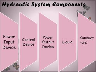
HYDRAULIC SYSTEM-CYLINDERS
Hydraulic control system.Understanding cylinders

HYDRAULIC SYSTEM-CYLINDERS
E N D
Presentation Transcript
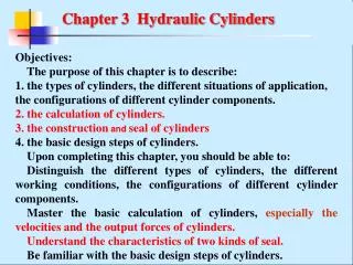
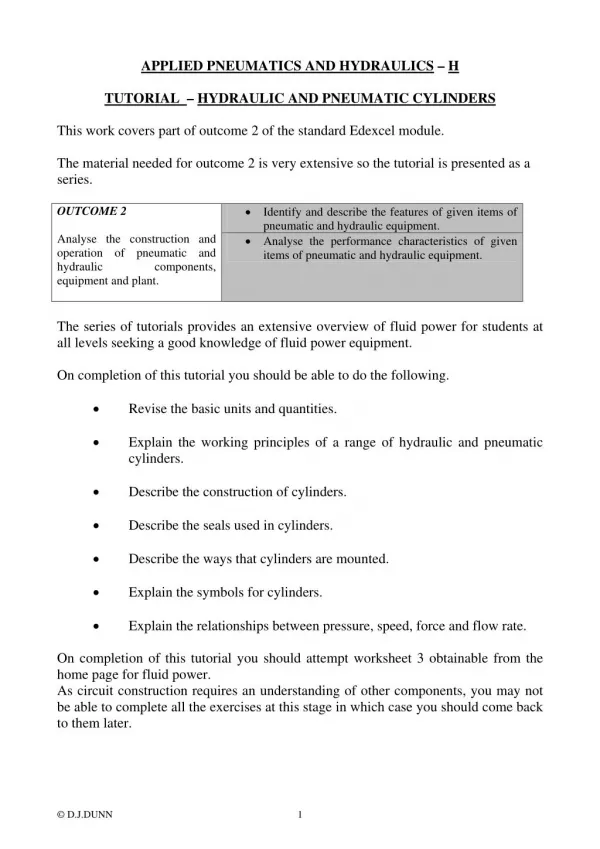
APPLIED PNEUMATICS AND HYDRAULICS – H TUTORIAL – HYDRAULIC AND PNEUMATIC CYLINDERS This work covers part of outcome 2 of the standard Edexcel module. The material needed for outcome 2 is very extensive so the tutorial is presented as a series. •Identify and describe the features of given items of pneumatic and hydraulic equipment. Analyse the construction and operation of pneumatic and hydraulic components, equipment and plant. The series of tutorials provides an extensive overview of fluid power for students at all levels seeking a good knowledge of fluid power equipment. On completion of this tutorial you should be able to do the following. • Revise the basic units and quantities. • Explain the working principles of a range of hydraulic and pneumatic cylinders. • Describe the construction of cylinders. • Describe the seals used in cylinders. • Describe the ways that cylinders are mounted. • Explain the symbols for cylinders. • Explain the relationships between pressure, speed, force and flow rate. On completion of this tutorial you should attempt worksheet 3 obtainable from the home page for fluid power. As circuit construction requires an understanding of other components, you may not be able to complete all the exercises at this stage in which case you should come back to them later. OUTCOME 2 •Analyse the performance characteristics of given items of pneumatic and hydraulic equipment. © D.J.DUNN 1
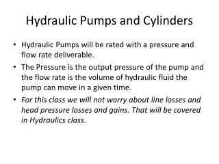
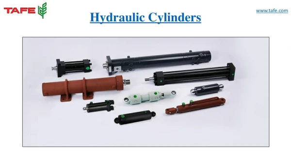
1. Cylinders are linear actuators which convert fluid power into mechanical power. They are also known as JACKS or RAMS. Hydraulic cylinders are used at high pressures and produce large forces and precise movement. For this reason they are constructed of strong materials such as steel and designed to withstand large forces. Because gas is an expansive substance, it is dangerous to use pneumatic cylinders at high pressures so they are limited to about 10 bar pressure. Consequently they are constructed from lighter materials such as aluminium and brass. Because gas is a compressible substance, the motion of a pneumatic cylinder is hard to control precisely. The basic theory for hydraulic and pneumatic cylinders is otherwise the same. 2. THEORY 2.1 FORCE The fluid pushes against the face of the piston and produces a force. The force produced is given by the formula: F = pA p is the pressure in N/m2 and A is the area the pressure acts on in m2. This assumes that the pressure on the other side of the piston is negligible. The diagram shows a double acting cylinder. In this case the pressure on the other side is usually atmospheric so if p is a gauge pressure we need not worry about the atmospheric pressure. INTRODUCTION Figure 1 Let A be the full area of the piston and a be the cross sectional area of the rod. If the pressure is acting on the rod side, then the area on which the pressure acts is is (A - a). F = pA on the full area of piston. F = p(A-a) on the rod side. This force acting on the load is often less because of friction between the seals and both the piston and piston rod. © D.J.DUNN 2
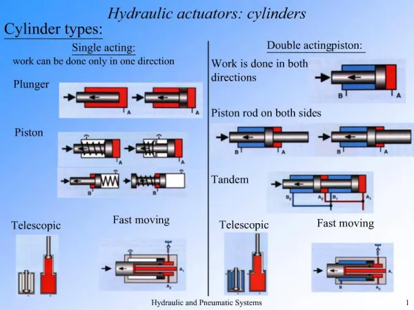
2.2 SPEED The speed of the piston and rod depends upon the flow rate of fluid. The volume per second entering the cylinder must be the change in volume per second inside. It follows then that: Q m3/s = Area x distance moved per second Q m3/s = A x velocity (full side) Q m3/s = (A-a) x velocity (rod side) Note in calculus form velocity is given by v = A dx/dt and this is useful in control applications. In the case of air cylinders, it must be remembered that Q is the volume of compressed air and this changes with pressure so any variation in pressure will cause a variation in the velocity. 2.3 POWER Mechanical power is defined as Force x velocity. This makes it easy to calculate the power of a cylinder. The fluid power supplied is more than the mechanical power output because of friction between the sliding parts. P = F v Watts 2.4 SINGLE ACTING CYLINDERS A simple single acting cylinder is shown below. The cylinder is only powered in one direction and needs another force to return it such as an external load (e.g. in a car hoist or jack) or a spring. No hydraulic fluid is present on the low pressure side. Single Acting Cylinder for Pushing Single Acting Cylinder for Pulling Figure 2 © D.J.DUNN 3
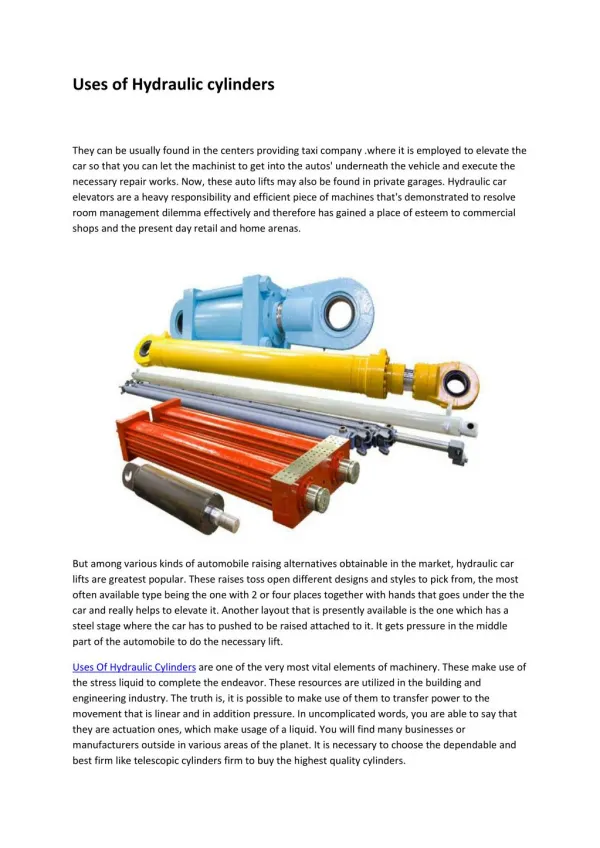
2.5 DOUBLE ROD CYLINDERS The basic design of a double rod cylinder is shown below. The design allows equal force and speed in both directions. It is useful in robotic mechanisms were the rod is clamped at both ends and the body moves instead. Figure 3 2.6TELESCOPIC CYLINDERS These cylinders produce long strokes from an initial short length. Each section slides inside a larger section. These cylinders have from 2 to five stages. They are typically used in refuse lorries for ejecting the compacted refuse. They are also used for lifts, tipping platforms, lifting platforms and other commercial vehicle applications. Figure 4 © D.J.DUNN 4
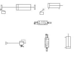
3. The detailed diagram shows a double acting cylinder. The main seals used are 1. Piston seals to prevent leakage from one side to the other. 2. Rod seal to prevent leakage from the rod end. 3. Static seals to prevent leakage from joints between the barrel and end caps. 4. Wiper seal to stop dirt being drawn inside with the rod. The bearings are 1.The rod end bearing made of brass or bronze. This takes the side loads on the rod and ensures lubrication and reduced wear. It also prevents the seal distorting and leaking. 2.The pistons bearing to take the sideways forces and reduce wear. SEALS AND BEARINGS Figure 5 4. SYMBOLS Figure 6 © D.J.DUNN 5
5. BUCKLING Buckling occurs when the rod bends or bows out sideways under load. The longer and thinner the rod, the more likely it is for buckling to occur. When selecting a cylinder from a catalogue, the manufacturer will show information to enable you to determine the buckling load. 6. CONSTRUCTION The detailed diagram shows the main construction details. Hydraulic cylinders are built to withstand substantial pressures and so are expensive compared to pneumatic cylinders. The body is a tube or barrel with a smooth finish to prevent seals wearing out. Steel is usually used for the strength required. The fluid ports are contained in the end caps. One end cap has a hole for the rod. The end caps must be sealed to the barrel. The picture shows cylinders with tie rods for holding the end caps in place. Figure 7 The next picture shows cylinders with the end caps screwed onto the barrel. Figure 8 Other methods of construction use welding and swaging techniques. These types cannot be disassembled for servicing. In some applications no fasteners are needed and external restraints prevent the end caps blowing out. © D.J.DUNN 6
6. CUSHIONING Figure 9 The fluid is normally expelled through the outlet port direct but when the cushioning boss enters the recess, the fluid around the piston is trapped. The only way the fluid can escape is through the secondary path, which is restricted by a needle valve. The needle valve is adjusted so that the piston is slowed up over the last part of its stroke by a pressure build up in the fluid escaping past the needle valve. 7. QUICK START The problem with cushioning is that when you try to move the piston back the other way, fluid only has the cushioning boss to push on and because it is a small area the force may not be enough to move it or it may only move slowly until the boss clears the recess. To get around this a one way check valve is placed in parallel with the needle valve so that fluid can easily get into the space behind the piston and push on the full area. 8. END FIXINGS The diagram shows typical ways of mounting cylinders and attaching them to machines. Figure 10 © D.J.DUNN 7
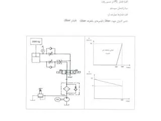
9. The basic method of controlling the speed is by controlling the flow in or out of the cylinder. The simplest way is to place a restrictor on the appropriate port but this reduces the thrust and wastes energy through friction. One of the problems with pneumatics is the compressibility of the air which makes it unsuitable for precise movement control in applications such as machine tools and robots. This problem is overcome by the use of air/oil systems (covered later). The cylinder is filled with oil and both ports are connected to a storage vessel with oil in them. The oil in these vessels has air supplied to the top. When air pressure is supplied to one tank, the oil is forced into the cylinder. The pressures are low and the cylinders are often pneumatic cylinders. The speed is controlled by a one way variable restrictor on each port. This system has the cost benefit and flexibility of a pneumatic system but with the precise and steady motion of hydraulics. WORKED EXAMPLE No.1 A double acting hydraulic cylinder has a bore of 100 mm. The rod is 40 mm diameter and the stroke is 120 mm. It must produce a pushing force of 12 kN. The flow rate available in both directions is 12 dm3/min. Calculate: i. The system pressure needed. ii. The force with which it pulls given the same pressure. iii. The speed on the outward stroke. iv. The speed of retraction. v. The power used on the outstroke. Assume ideal conditions throughout. SOLUTION A = πD2/4 = π x 0.12/4 = 7.854 x 10⁻³ m2 p = F/A = 12000/ 7.854 x 10-3 = 1.528 x 10⁶ N/m2 = or 1.528 MPa a = πd2/4 = π x 0.042/4 = 1.257 x 10⁻³ m2 Pulling force = p(A-a) = 1.528 x 106 x (7.854 x 10-3 - 1.257 x 10⁻³) = 10008 N Flow rate Q = 0.012/60 = 20 x 10-3 m3/s Speed on the outward stroke = Q/A = 20 x 10-3 / 7.854 x 10-3 = 0.025 m/s or 25 mm/s Speed of retraction = Q/(A-a) = 20 x 10-3/( 7.854 x 10⁻³ - 5.027 x 10⁻³) = 0.03 m/s or 30 mm/s Power = pQ = 1.528 x 106 x 20 x 10-3 = 305.6 Watts CYLINDER SPEED CONTROL © D.J.DUNN 8
1. A double acting hydraulic cylinder with a single rod must produce a thrust of 80 kN and move out with a velocity of 3 mm/s on the out stroke (positive stroke). The operating pressure is 100 bar gauge. Calculate the bore diameter required and the flow rate of the oil. (Answers 101 mm and 24 cm3/s) 2. The cylinder in question has a rod diameter 25 mm. If the flow rate and pressure are the same on the retraction (negative) stroke, what would be the force and speed available? (Answers 75 kN and 3.2 mm/s) 3. A single acting hydraulic cylinder has a piston 75 mm diameter and is supplied with oil at 80 bar gauge and 0.265 dm3/s. Calculate the thrust, velocity and power. (Answers 62.83 kN, 34 mm/s and 2.12 kW) SELF ASSESSMENT EXERCISE No.1 © D.J.DUNN 9
SELF ASSESSMENT EXERCISE No.2 Identify by name the parts of a typical pneumatic cylinder shown on the diagram. Figure 11 1. _______________________________________________ 2. _______________________________________________ 3. _______________________________________________ 4. _______________________________________________ 5. _______________________________________________ 6. _______________________________________________ 7. _______________________________________________ 8. _______________________________________________ 9. _______________________________________________ 10. _______________________________________________ 11. _______________________________________________ Answers 1- Rear end cap. 2- Quick stat valve. 3- Piston. 4- Draw bolt. 5- Rod bearing. 6- Rod. 7- Wiper ring. 8-Front end cap. 9- Piston seal. 10- Low friction bearing ring. 11- Cushioning boss seal. 12- Cushioning valve. © D.J.DUNN 10
EXERCISE INTRODUCTION TO PNEUSIM PRO™ ™ PneusimPro is a professional software package that enables you to construct various forms of circuits, programme them and test them by simulation. PART 1 BASIC MANUAL PNEUMATIC CIRCUIT Although you may not be familiar with the symbols used in pneumatic circuits, you should be able to construct the circuit below under instruction from your lecturer. Open the pneumatic library. Choose Actuators – double acting cylinder and drag the symbol onto the screen. Choose directional valves 4/2 (14) and drag the symbol onto the screen. Add the lever and spring as directed. Choose lines and select exhaust and pressure source symbols and add them to the valve. Select pressure lines and connect the symbols as instructed. Under tools select verify connections. There should be none. Click on the green button and run your simulation. Use the hand to operate the valve and you should be able to make the cylinder go in and out. Figure 12 On the tool bar select document – page layout – documentation. Click border, map locator, title block and bill of materials. Re-position your diagram if necessary – ask how. Using the text tools, add your name in the appropriate box – ask how. Print off a copy of the drawing. © D.J.DUNN 11
PART 2 ELECTRO-PNEUMATIC CIRCUIT Modify your circuit as follows. Double click on the valve and delete the lever and spring. Add the spring and solenoid. Enter SOL1 as the tag name of the solenoid. Open the workshop electrical control (Europe). Construct the electrical circuit as shown using power supplies – 24 V and 0V, switches –toggle switch NO (Normally Open) and output components – Solenoid. Give the toggle switch the tag name TS1 and the solenoid SOL1. Figure 13 Run the simulation and operate TS1 with the hand to make the actuator go in and out. PART 3 AUTOMATIC ELECTRO-PNEUMATIC CIRCUIT Modify your circuit by adding SOL2. Change the switch to a push button N/O (PB1). Add the proximity sensors PS1 to both parts of the circuit. Look in sensors. Figure 14 © D.J.DUNN 12
Run the simulation and when you momentarily operate PB1 the cylinder should extend and when PS1 is activated it should automatically return. Using the text tools, complete the title block and print off a copy of your drawing. This must be attached for marking. PART 4 INTERFACING TO A REAL SYSTEM Figure 15 Construct the circuit as shown. Run the simulation to show that operating the button makes the cylinder go out (+) and in (-) Now modify your circuit using copy and paste to produce three identical circuits but one will use the tag A, the next B and the third C. This is an actual representation of a pneumatic circuit that you can see by the computer. The computer is connected to solenoids by a cable and interface. When you operate the simulation, not only will you see it working on the screen but also in reality. The interface gives real control over real pneumatics. © D.J.DUNN 13
A+ A- B+ B- C+ C- 24V PBA PBA PBB PBB PBC PBC A+ A- B+ B- C+ C- IN OUT 0 0 1 1 2 2 0V 3 3 4 4 5 5 6 6 7 7 Figure 16 Add the interface from the interface workshop. Double click on it and label OUT 0 as A+, OUT 1 as PBA, OUT 2 as PBB and OUT 3 as PBC. This will tell the interface which connection is which in the real world. Run the equipment and simulation and demonstrate it working. Print off a copy of your drawing as evidence. Make sure that your tutor signs here to verify that you have done the work. © D.J.DUNN 14