Lecture 5- Tyre Modelling
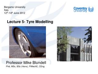
Bergamo University Italy 12 th -14 th June 2012. Lecture 5- Tyre Modelling. Professor Mike Blundell Phd , MSc, BSc ( Hons ), FIMechE , CEng. Contents. History and Tyre Construction Tyre Force and Moment Generation

Lecture 5- Tyre Modelling
E N D
Presentation Transcript
Bergamo University Italy 12th-14th June 2012 Lecture 5- Tyre Modelling Professor Mike Blundell Phd, MSc, BSc (Hons), FIMechE, CEng
Contents • History and Tyre Construction • Tyre Force and Moment Generation • Tyre Models for Handling and Durability (MF Tyre Model, Finite Element models, Ftire) • Aircraft Tyre Modelling • New Developments
History of Tyres The first pneumatic tyre, 1845 by Robert William Thomson. A number of air filled tube inside a leather case. Resistant to punctures but old solid rubber remained in favour with the public. http://www.blackcircles.com/general/history Boyd Dunlop reinvented the pneumatic tyre whilst trying to improve his sons bike in1888 http://www.blackcircles.com/general/history In 1895 the pneumatic tyre was first used on automobiles, by Andre and Edouard Michelin. http://www.blackcircles.com/general/history http://polymerprojecttopics.blogspot.com/2010/08/radial-tyre-vs-bias-tyre.html Michelin first announced the Tweel in 2005, a non-pneumatic tyre, removing the necessity checking tyre pressures http://auto.howstuffworks.com/tweel-airless-tire.htm Michelin first introduced steel-belted radial tires in Europe in 1948 http://polymerprojecttopics.blogspot.com/2010/08/radial-tyre-vs-bias-tyre.html
Tyre Sidewall Information 205/55 R15 87V 205 Nominal Section-width in mm TUBELESS Tubeless / Tube Type E4 All passenger car tyres from current production comply with ECE Standard 30 026504 Approval number acc. To ECE regulation 30 4008 Production code (40th week, 2008 DOT Department of Transportation, USA TWI Tread Wear Indicator (1.6mm) Continental Technical Data Book. Car Tyres 1999
Tyres for All Seasons • Motorsport -Slicks -Intermidiates -Full Wets • Passenger Cars -Summer Tyres -All Season Tyres -Winter Tyres -Mud and Snow Tyres
Radial Tyre Structure http://www.dunlopatl.co.uk/tech_support/aircraft-tyre-technology.aspx http://www.hankooktire-eu.com/technology/types-of-tires/according-to-structure.html
Rubber Compound Formulation • Two Major Ingredients – the rubber and the filler (carbon black and silica) • Combined to achieve different objectives – maximise wet and dry traction/ achieve superior rolling resistance • Four major types of rubber • natural rubber • styrene-butadiene rubber (SBR) • polybutadiene rubber (BR) • butyl rubber (along with halogenated butyl rubber) • The first three are primarily used as tread and sidewall compounds, while butyl rubber and halogenated butyl rubber are primarily used for the inner liner • Other ingredients also come into play to aid in the processing of the tire or to function as anti-oxidants, anti-ozonants, and anti-aging agents. In addition, the “cure package”—a combination of curatives and accelerators—is used to form the tire and give it its elasticity.
Tyre Thread Design http://www.checkthatcar.com/tyre%20anatomy.asp Rib Shape Lug Shape Rib-Lug Shape Groove Studs: Further improvement of grip in icy conditions http://www.hankooktire-eu.com/technology/types-of-tires/according-to-season.html Sipe: Fine groove in the tread pattern to improve grip in icy conditions Block Shape Asymmetric pattern Directional pattern http://www.ctyres.co.uk/tyre_info/tyre_type.html
FEA Tyre Models http://www.cosin.eu/
Automotive Applications • Main applications are in the automotive industry for: • Simulation of vehicle handling • Prediction of vehicle ride quality • Determination of component loads from systems model
Aerospace Applications • There is a growing need in the aerospace industry for: • Prediction of shimmy • Rough field performance • Ride & controllability • Ground loads • Landing, Takeoff, Taxiing
γ Angular Velocity (ω) Wheel Torque (T) Spin Axis Direction of Wheel Heading Tractive Force (Fx) WC {Xsae}1 α {V}1 Direction of Wheel Travel P {Ysae}1 Normal Force (Fz) {Zsae}1 Lateral Force (Fy) SAE Tyre Axis System
Direction of Sliding Tyre Material Adhesive Forces due to Molecular Bonding Road Surface Frictional Force Component due to Adhesion
Tyre Testing • Lateral force with slip/camber angle • Aligning moment with slip/camber angle • Longitudinal force with slip ratio Fy Slip Angle Courtesy of Dunlop TYRES Ltd.
Lateral Force Fy with Slip Angle α Courtesy of Dunlop Tyres Ltd.
Tyre Modelling • Prediction of Vehicle Ride Quality • -Simple Physical Models (Stiffness/Damping) • -More Advanced Physical Models (FTire) Simulation of Vehicle Handling • -Interpolation models (Lookup Tables) • -Simple Equation based representations (Fiala) • -Complex Mathematical Fits to Test Data (Magic Formula) • -Pure and Combined Slip Models • Determination of Component Loading • -Simple Physical Models (Equivalent Volume) • -More Advanced Physical Models (FTire) • -Full Non-Linear Finite Element Models
Tyre Model Fx Fy Tyre Model Mz Fx Fy Fz Mz Fz Vehicle/Tyre Model Interaction VEHICLE MODEL Wheel centre - Position, Orientation and Velocities Mathematical Solution at Integration Time Steps TYRE MODEL Fx - longitudinal tractive or braking force Fy - lateral cornering force Fz - vertical normal force Mz - aligning moment Mx - overturning moment My - rolling resistance moment
Fy FIALA MODEL INTERPOLATION MODELS MAGIC FORMULA MODELS Check plots in ADAMS tyre rig model Slip Angle a Vehicle Model Tyre Model/Data Assessment
Tyre Model Summary • Interpolation Model • It uses tyre test data to interpolate results for a particular scenario • Empirical Model • Empirical models use test data to determine equations and parameters to replicate the tyre data • Physical Model • These use physical representations of tyre to generate results (e.g. radial belts with spring elements) 21
2 R2 Tyre Dimensions Model Geometry R2 R1 R1 The Fiala Tyre Model • Input Parameters
The Fiala Tyre Model Input Parameters R1 The unloaded tyre radius R2 The tyre carcass radius kz The tyre radial stiffness Cs The longitudinal tyre stiffness Ca Lateral tyre stiffness due to slip angle Cg Lateral tyre stiffness due to camber angle (Not Used) Cr The rolling resistant moment coefficient ζ The radial damping ratio m0 The tyre to road coefficient of “static” friction m1 The tyre to road coefficient of “sliding” friction
The Fiala Tyre Model(Lateral Force and Aligning Moment) • Example of the Lateral Force Generation The critical slip angle is: And so if |α|<α* then: Else if |α|>α* then: • Example of the Aligning Moment Generation And so if |α|<α* then: Else if |α|>α* then:
The Fiala Tyre Model • Limitations • No camber thrust • Not suitable for combined slip • Constant cornering stiffness with load • Zero aligning moment at high slip angles
The “Magic Formula” Tyre Model The basis of this established model is that tyre force and moment curves look like sine functions which have been modified by introducing an arctangent function to “stretch” the slip values on the x-axis. Fx Slip Anglea Slip Ratiok Mz Fy (1) Bakker E., Nyborg L. & Pacejka, H.B., Tyre modelling for use in vehicle dynamics studies, SAE paper 870421. (2) Bakker E., Pacejka H.B. & Linder L., A new tyre model with application in vehicle dynamics studies", SAE paper 800087, 4th Auto Technologies Conference, Monte Carlo, 1989.
Y y D ys arctan (BCD) Sv x X Sh The “Magic Formula” Tyre Model The general form of the model (version 3) is: y(x) = D sin [ C arctan{ Bx - E ( Bx - arctan ( Bx ))}] where Y(X) = y(x) + Sv Y = Fx, Fy, or Mz x = X + ShX =a or k Sh = horizontal shift Sv = vertical shift
The “Magic Formula” Tyre Model The Main Parameters in the General Equation are D - is the peak value. C - is a shape factor that controls the “stretching” in the x direction. 1.30 - lateral force curve. 1.65 - longitudinal braking force curve. 2.40 - aligning moment curve. B - is referred to as a “stiffness” factor. BCD is the slope at zero slip. E - is a “curvature” factor which effects the transition in the curve and the position xm at which the peak value if present occurs. E is calculated using: Bxm - tan ( p / 2C) E = Bxm - arctan ( Bxm ) ys - is the asymptotic value at large slip values and is found using: ys = D sin ( p C / 2)
BCDy (N/rad) a3 arctan (2a3/a4) 0 a4 Fz (N) The “Magic Formula” Tyre Model At zero camber the cornering stiffness BCDy reaches a maximum value defined by the coefficient a3 at a given value of vertical load Fz which equates to the coefficient a4. The slope at zero vertical load is taken as 2a3/a4.
General Formula (Version 3) y(x)=Dsin[Carctan{Bx-E(Bx-arctan(Bx))] Y(X) = y(x) + Sv x = X + Sh B = stiffness factor C = shape factor D = peak factor Sh = horizontal shift Sh = vertical shift B= dy/dx(x=0) / CD C = (2/p) arcsin (ys/D) D = ymax E = (Bxm-tan(p/2C))/(Bxm - arctan (Bxm)) Lateral Force Xy = a Yy = Fy Dy = my Fz my = (a1Fz + a2) (1 - a15 g2) BCDy = a3 sin(2 arctan(Fz/a4)) (1 - a15| g |) Cy = a0 Ey = (a6Fz+a7) (1-(a16g + a17)sgn(a + Shy)) By = BCDy / CyDy Shy = a8Fz + a9 + a10g Svy = a11Fz + a12 + (a13Fz2 + a14Fz)g The “Magic Formula” Tyre Model
Longitudinal Force Xx = k Yx = Fx Dx = mx Fz mx = b1Fz + b2 BCDx = (b3 Fz2 + b4Fz) exp(-b5Fz) Cx = b0 Ex = (b6Fz2 + b7Fz + b8)(1-b13sgn(k + Shx)) Bx = BCDx / CxDx Shx = b9Fz + b10 Svy = b11Fz + b12 Brake force only (b11 = b12 = b13 = 0) Aligning Moment Xz = a Yz = Mz Dz = (c1Fz2 + c2Fz) (1 - c18g2) BCDz = (c3Fz2+c4Fz)(1- c6 | g |)exp (-c5Fz) Cz = c0 Ez = (czFz2 + c8Fz + c0) (1 - (c19g + c20)* *sgn(a + Shz)) / (1 - c10 | g | ) Bz = BCDz / CzDz Shz = c11Fz + c12 + c13g Svz = c14Fz + c15 + (c16Fz2 + c17Fz)g The “Magic Formula” Tyre Model
Laboratory Simulation- Shaker Rig RIDE AND VIBRATION Simple Spring Damper Model Flexible Ring Method Modal FE Model in MBS
Vehicle Body or Sprung Mass z m Body Response Suspension Spring and Damper k c Zg Z Ground Input X Time (s) Ride Simulation (Comfort) Also important in Motorsport Vehicles Also important in Military Vehicles
Fy Lateral loads Fx Longitudinal loads Fz Vertical loads Component Load Prediction FINITE ELEMENT MODEL ADAMS MODEL Tyre Modelling Radial Spring Models Equivalent Plane Method Equivalent Volume Method Flexible Ring Method Coupled Explicit FE and MBS Methods
Tyre Modelling FINITE ELEMENT MODELS A Physical Tyre Model is required Finite Element Modelling is an example Can model deformable terrain as well Not practical in terms of modelling time Excessive computational effort Mainly a tool for Tyre Manufacturers
Contact Forces • Used on Helisafe EU project and for tracked vehicles • Modelled hard non-destructive landings • Bi-linear model with tyre and wheel stiffness • Contact function based on stiffness and damping • Includes friction Eurocopter Model 5m/s ground impact Tracked Vehicle operating in deep snow
Durability Tyre Models • Early durability tyre models were 2D • Radial Spring or Equivalent Plane • Capture deformed shape of tyre enveloping terrain • Resultant force towards wheel centre Radial Spring Model Equivalent Plane
Tyre centre line Tyre cross-sectional elements Input points to define shape Tyre centre line Durability Tyre Model • Originally developed in Finland for logging vehicles • Captured tyre interaction with sawn tree trunks on rough terrain • 3d Model - Discritization into cross-sectional elements Definition of tyre carcass shape for a durability tyre model
3 4 2 5 1 6 Early Road/Terrain Model Road modelled using triangular planar elements Friction can vary on element by element basis Intersection of tyre sectional elements with road elements
A Tyre Model for Ride & Durability Simulations A Flexible ring tyre model Tire phenomena based on a mechanical model The FTIRE Model Developed by Cosin (www.cosin.eu) FTire on Belgian Pave
The FTIRE Model • Structural dynamics based, full 3D nonlinear in-plane and out-of-plane tire model for simulation of belt dynamics, local pressure distribution in the contact patch, rolling resistance, side-wall contact, large camber angles and misuse scenarios. • Suitable for a frequency range up to 200Hz, excited by short surface wavelength, mass imbalance, non-uniformity or irregular tread patterns. • Very fast and flexible. Orders of magnitude faster than explicit FE models. • Simulation of imbalances by inhomogeneous mass distribution and local wear. • Belt temperature distribution model.
The FTIRE Model Tyre structure described with distributed mass, connected to rim by distributed stiffness & damping elements bending stiffness both in-plane and out-of-plane c bend. c c belt rad. c tang. (simplified)
3D Road/Terrain Model Open Source software developed by Daimler AG VIRES GmbH 3D Road Data Curved regular Grid (CRG) Representation Data Files can be generated from laser scans along a road Regular Grid Road Data Files (RGR Files) Belgian Block XYZ map Open CRG Visualisation
FTire Animations Detailed Tread Pattern Truck Tire Passing a big bump
FTire Animations Local Belt Deformation Rolling over a high kerb
FTire Animations Sine wave with decreasing wave length FTire on RGR Road Surface
10 mm 200 mm FTire: Running over an Obstacle v = 80 km/h 5000 2000 1000 4000 0 3000 -1000 2000 -2000 1000 0 0.02 0.04 0.06 0.08 0.1 0 0.02 0.04 0.06 0.08 0.1 longitudinal force [N] wheel load [N]
side force aligning torque M [Nm] z F [N] y 200 8000 7000 150 6000 100 5000 50 4000 3000 0 2000 -50 1000 -100 0 0 5 10 15 20 25 30 35 40 45 0 5 10 15 20 25 30 35 40 45 side-slip angle [deg] side-slip angle [deg] FTire: Handling Characteristics Fz = 2, 4, 6, 8 kN
Aircraft Tyre Modelling • EPSRC Project with AIRBUS UK • Simulate landing, takeoff, taxiing • Tyre Testing by Airbus in Toulouse • Developed model in a MATLAB/SIMULINK Environment with export to ADAMS • Low Parameter Model based on Harty Approach with extended Load/Speed dependence • Shimmy Modelling (Early NASA work) remains elusive