Download

1 / 45
610 likes | 1.37k Vues
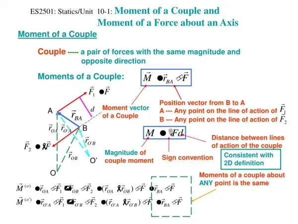
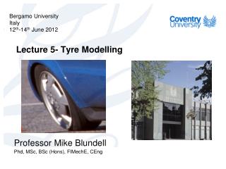
m t. c z. k z. P. δ z. {X sae } 1. {Z sae } 1. Bergamo University Italy 12 th -14 th June 2012. Lecture 6 – Tyre Force and Moment Characteristics. Professor Mike Blundell Phd , MSc, BSc ( Hons ), FIMechE , CEng. γ. Angular Velocity ( ω ) Wheel Torque (T). Spin Axis.

E N D
mt cz kz P δz {Xsae}1 {Zsae}1 Bergamo University Italy 12th-14th June 2012 Lecture 6 – Tyre Force and Moment Characteristics Professor Mike Blundell Phd, MSc, BSc (Hons), FIMechE, CEng
γ Angular Velocity (ω) Wheel Torque (T) Spin Axis Direction of Wheel Heading Tractive Force (Fx) WC {Xsae}1 α {V}1 Direction of Wheel Travel P {Ysae}1 Normal Force (Fz) {Zsae}1 Lateral Force (Fy) SAE Tyre Axis System
{Ziso}1 Normal Force (Fz) γ Angular Velocity (ω) Wheel Torque (T) Spin Axis Direction of Wheel Heading Tractive Force (Fx) WC {Yiso}1 {Xiso}1 α Lateral Force (Fy) {V}1 Direction of Wheel Travel P ISO Tyre Axis System
ω V Ru Rl Re Rear Front B A C P Definition of Tyre Radii
Left XSAE FY YSAE Direction of Travel FY Right XSAE YSAE Generation of Tyre Lateral Forces due to Conicity
XSAE Left YSAE YSAE YSAE YSAE FY FY FY FY Direction of Travel Right XSAE Generation of Tyre Lateral Forces due to Plysteer
Direction of Sliding Tyre Material Adhesive Forces due to Molecular Bonding Road Surface Frictional Force Component due to Adhesion
F F δ Loading Unloading δ Hysteresis in Rubber
Direction of Sliding Loading Unloading Road Surface Loading and Unloading of Tyre Rubber in the Contact Patch
Over Inflation Normal Inflation Under Inflation Pressure Distribution in the Tyre Contact Patch Tyre Contact Patch Pressure Distribution in a Stationary Tyre Contact Patch
γ Spin Axis Overturning Moment (Mx) Tractive Force (Fx) WC {Xsae}1 α Rolling Resistance Moment (My) P Self Aligning Moment (My) {Ysae}1 Lateral Force (Fy) {Zsae}1 Normal Force (Fz) Tyre Forces and Moments Shown Acting in the SAE Tyre Axis System
Fx Fx Fy Tz Longitudinal Stiffness Lateral Stiffness Torsional Stiffness φ δx δx δy φ Fy δy Tz Measurement of Stiffness in a Non-Rolling Tyre
mt cz kz P δz {Xsae}1 {Zsae}1 Vertical Tyre Force Model Based on a Linear Spring Damper
ω V= ω Re O Ru Tread Material Re Rl Vt = ω Ru Vt = ω Ru Compression A C D B Front P Rear {Xsae}1 Vt = ω Re Tangential velocity of tread relative to O Vt = ω Rl Vt = ω Re Direction of slip relative to the road surface Longitudinal Shear Stress Generation of Slip in a Free Rolling Tyre
Un-deformed Tyre Deformed Tyre Front Rear Squirm through the contact patch (Gillespie, 1992) Lateral slip movement (Moore, 1975) Lateral Distortion of the Contact Patch for a Free Rolling Tyre
ω Fz O FRx Rl My = Fz δx FRx P Rear Front {Xsae}1 δx Fz Generation of Rolling Resistance in a Free Rolling Tyre
ω TB V = ω Re O Rear Front Tread Def. Tension Compression FB {Xsae}1 δx Fz Pressure Distribution Longitudinal Slip Longitudinal Shear Stress Generation of Force in a Braked Tyre
Braking Force Fx (N) Braking Force versus Slip Ratio Slip Angle = 0 Camber Angle = 0 Fz = -8 kN Fz = -6 kN Fz = -4 kN Fz = -2 kN Longitudinal Stiffness Cs = tan φ φ 0.0 Slip Ratio 1.0 Braking Force versus Slip Ratio
Braking Force Fx (N) Braking Force versus Slip Ratio Slip Angle = 0 Camber Angle = 0 Dry Road Good Tread on Wet Road Poor Tread on Wet Road Aquaplaning 0.0 Slip Ratio 1.0 The Effect of Road Contamination on Braking
ω TD V = ω Re O Front Rear Tread Def. Tension Compression δx FD {Xsae}1 Fz Pressure Distribution Longitudinal Slip Longitudinal Shear Stress Generation of Force in a Driven Tyre
Slip Angle Camber Angle γ Lateral Force Camber Thrust Lateral Force Pneumatic Trail Camber Thrust Aligning Moment due to camber angle Aligning Moment due to slip angle α Direction of Travel Direction of Travel Forces and Moments due to Slip and Camber Angle
Pressure p Side View Limit Lateral Stress μp Slipping Starts Lateral Stress Tyre Contact Patch Front Rear Mz = Fy xpt Fy Top View Slipping Starts Lateral Stress Direction of Wheel Heading α xpt Direction of Wheel Travel Pneumatic Trail Generation of Lateral Force and Aligning Moment due to Slip Angle
Lateral Force Fy (N) Lateral Force versus Slip Angle Camber Angle = 0 Fz = -8 kN Fz = -6 kN Fz = -4 kN Fz = -2 kN Cornering Stiffness Cs = tan φ φ -Slip Angle α (degrees) Plotting Lateral Force versus Slip Angle
Aligning Moment Mz (Nm) Aligning Moment versus Slip Angle Camber Angle = 0 Fz = -8 kN Fz = -6 kN Fz = -4 kN Aligning Moment Stiffness = tan φ Fz = -2 kN φ Slip Angle α (degrees) Plotting Aligning Moment versus Slip Angle
γ Spin Axis {Ysae}1 Camber Thrust Fy {Zsae}1 Tyre Load Fz Resultant Force FR Generation of Lateral Force due to Camber Angle
Lateral Force Fy (N) Lateral Force versus Camber Angle Slip Angle = 0 Fz = -8 kN Fz = -6 kN Fz = -4 kN Fz = -2 kN Camber Stiffness Cγ = tan φ φ Camber Angle γ (degrees) Plotting Lateral Force versus Camber Angle
γ Spin Axis {Ysae}1 Camber Thrust Fy A B C {Zsae}1 Rear C A B C A {Ysae}1 Fy Mz Front {Xsae}1 C B A Generation of Self Aligning Moment due to Camber Angle
Aligning Moment Mz (Nm) Aligning Moment versus Camber Angle Slip Angle = 0 Fz = -8 kN Fz = -6 kN Fz = -4 kN Fz = -2 kN Aligning Moment Camber Stiffness = tan φ φ Camber Angle γ (degrees) Plotting Aligning Moment Versus Camber Angle
Lateral Force Fy (N) Lateral Force versus Slip Angle -Slip Angle α (degrees) Camber Angle = 0 Camber Angle = 5 Camber Angle = 10 The Effect of Combined Camber and Slip Angle on Lateral Force
Camber Angle Slip Angle Wheel Plane O Wheel Centre O Mx=Fzδy Mx = Fz δy YSAE YSAE P P dy dy Fz ZSAE ZSAE Fz Generation of Overturning Moment in the Tyre Contact Patch
Fy YSAE Fx = μ Fz Direction of Travel XSAE Contact Patch S Maximum Braking Force Fx = μ Fz Pure Braking Fy Maximum Cornering Force Fy = μ Fz Fy = μ Fz YSAE α Contact Patch XSAE Large Slip Angle α Pure Cornering Direction of Travel Maximum Road Plane Force FR = μ Fz Fy YSAE XSAE Contact Patch Fx Large Slip Angle α Combined Braking and Cornering Direction of Travel Fy YSAE Contact Patch XSAE Braking Force Fx Moderate Slip Angle α Combined Braking and Cornering Direction of Travel Pure and Combined Braking and Cornering Forces
Lateral Force Fy C α =10 α =6 D Friction Circle α =4 Resultant Force FR α =2 α =1 Braking Force Fx Driving Force Fx A B Plotting Lateral Force Against Longitudinal Force (Friction Circle)
Lateral Force Fy (N) Lateral Force versus time Steady State Fymax 0.632 Fymax t2 t0 t1 Time (sec) t Development of Lateral Force Following Step Steering Input
Courtesy of Dunlop Tyres Ltd. High Speed Dynamics Machine for Tyre Testing Formerly at Dunlop Tyres Ltd.
Lateral Force Fy with Slip Angle α Courtesy of Dunlop Tyres Ltd.
Aligning Moment Mz with Slip Angle α Courtesy of Dunlop Tyres Ltd.
Lateral Force Fy with Aligning Moment Mz (Gough Plot) Courtesy of Dunlop Tyres Ltd.
Cornering Stiffness with Load Courtesy of Dunlop Tyres Ltd.
Aligning Stiffness with Load Courtesy of Dunlop Tyres Ltd.
Lateral Force Fy with Camber Angle α Courtesy of Dunlop Tyres Ltd.
Aligning Moment Mz with Camber Angle α Courtesy of Dunlop Tyres Ltd.
Camber Stiffness with Load Courtesy of Dunlop Tyres Ltd.
Aligning Camber Stiffness with Load Courtesy of Dunlop Tyres Ltd.