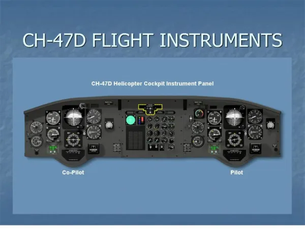
CH-47D Environmental Systems
CH-47D Environmental Systems. Hot Environment. Cold Environment. Terminal Learning Objective (TLO). Action : Describe the components, operational characteristics, functions and limitations of the CH-47D Environmental Systems Conditions : In a classroom, given a student handout

CH-47D Environmental Systems
E N D
Presentation Transcript
Terminal Learning Objective (TLO) • Action: Describe the components, operational characteristics, functions and limitations of the CH-47D Environmental Systems • Conditions: In a classroom, given a student handout • Standards: Correctly answer in writing, without reference, four of five questions pertaining to components, operational characteristics, limitations, and functions of the CH-47D Environmental System, IAW TM 1-1520-240-10 and the student handout
Terminal Learning Objective (TLO) – (Cont.) • Safety Requirements: None • Risk Assessment Level: Low • Environmental Considerations: None • Evaluation: Each student will be evaluated on this block of instruction during the third written examination. This will be a criterion type examination requiring a GO on each scored unit. You will have 90 minutes for the exam
Learning Step/Activity #1 • Describe components, functions, and operational characteristics of the Heating and Ventilating system
Heating and Ventilation System • Type: • 200,000 British Thermal Unit (BTU)/hr • Internal combustion system • Fuel Supply: • R/H Main tank • Consumes 15 PPH • Electrical Power: • 3 Phase AC • 28V DC • No.2 PDP
Cockpit Air Knobs • Located: • Outboard – Pilot/Co-Pilot • Purpose: • Regulates – Air flow to the cockpit
OPERATOR’S MANUAL - CAUTION • Pull out the cockpit air knobs Slowly to preclude dirt and debris from being blasted into the air and the pilot’s eyes Page: 8−4−1
Air Control Handles • Mounted: • R/H Side – Canted console • Two handles • Purpose: • Upper handle:- • Control Defogging/Defrosting • Bottom handle:- • Direct air to the cargo compartment
Intake Duct Low Pressure Line Exhaust Duct Blower Main Fuel Supply Line Differential Air Pressure Switch Spark Plug Adapter Assembly Fuel Control Combustion Chamber Ignition Unit Drain Line Heater Assembly R/H side Sta.95 and 120
Heater Assembly - Components • Combustor Chamber: • Inner and outer chamber • Passes air over heated chamber and discharge - Bottom • Spark Plug: • Ignition
Heater Drain • Combustor Drain: Sta.98 outside R/H • Drains unburned fuel overboard • Subject to ice accumulation • If the heater shuts down during icing:- Do Not Attempt to Restart
Fuel Control Main Fuel Supply Line Heater Fuel Supply Line Fuel Control Unit
Fuel Control (Cont.) • Mounted: • R/H side in the heater compartment • Purpose: • Supply and control fuel flow:- • Main fuel tank – Boost pumps • Filter assembly • Fuel pump – Raises fuel pressure – 100 PSI • Pressure relief valve • Solenoid valve
Exhaust System • Constructed: • Heat resistant steel • Connected– Bottom heater • Enclosed:- • Four piece shroud • Protects personnel – Exhaust surface • Outside – Helicopter (check for obstruction)
Exhaust System (Cont.) Heater Exhaust REMOVE COVERS PRIOR TO STARTING THE HEATER Heater Intake
Ignition Unit • Mounted: • Sta.95 R/H side • Purpose: • High voltage pulse –Spark plug • Contains: Replaceable fuse
Blower Assembly • Mounted between: • Intake duct • Heater assembly • Purpose: • Draws air – Intake Blower Assembly
Differential Air Pressure Switch • Mounted: • Heater compartment • Purpose: • Fuel flow • Ignition:- • Insufficient air
Heater Controls (Overhead Panel) • Function Switch: • Three Position:- • VENT BLOWER ONLY • OFF • HEATER ON • Heater Start Switch: • Press and Release Type • Time Delay:- • 10 – 15 Sec • Fuel • Ignition • Cabin Temperature Selector: • Controls cabin thermostat
Cabin Thermostat • Located: • L/H side Sta.355 cabin area • Function: • With temperature selector and controller • Maintain cabin temperature pre-selected temperature:- • Mercury filled – Heated 34°C • Removes power:- • Fuel solenoid valve
Heater Hot CautionLight • Located: Master caution panel • Indicates: Failure automatic temperature circuits • Heater – Shuts OFF • Blower – Continue RUN
Normal Operation − Starting • Inlet and outlet covers — Remove • BATT switch — ON • APU — Start (Para. 8-2-18) • APU GEN switch — ON. RECT OFF caution capsule extinguishes • R (Right) MAIN FUEL PUMP switches — ON • Heater function switch — Heater ON • HTR START switch — Press Page: 8-4-1
Stopping • Heater function switch—OFF • WaitTwo Minutes Before Turning Generator (s) Off • NOTE:After heating and ventilating system has been stopped with the generator (s) ON, the blower will continue to operate until the temperature within the heater combustion chamber is below 49°Cdegrees Page: 8-4-2
Heater Overheat Condition • Wait twominutes for cool down (Heater) • HTR START switch — Press • HEATER HOT caution — Monitor • The HEATER HOT caution light will not extinguish until combustion chamber temperature is below 177°Cand HTR START switch is pressed Page: 8-4-7
Learning Step/Activity #2 • Describe the operational characteristics and limitations of the Windshield Wipers
Windshield Wipers − Rotary Switch • Located: • Overhead control panel • Five Positions: • PARK • OFF • SLOW • MED • FAST
Wipers − Park Position • Park Position: • Stowed against the inside windshield frame • Operators Caution: • To prevent windshield damage, do not operate windshield wipers when windshield is dry • NOTE: • The windshield wipers shall be off at airspeeds above 130 knots Page: 2-9-3 Page: 5-5-1
Learning Step/Activity #3 • Describe the operational characteristics and limitations of the Windshields Anti-Ice
Windshield Anti-Ice • Provides: • Anti-Icing/Defogging:- • Pilot and Copilot windshield • Defogging:- • Center windshield • Transparent Conductive Coating Embedded: • Pilot • Center • Co-Pilot • Electrically heated
Temperature Controller • Located: • Nose compartment • Temperature Controller: • Interrupts:- • Electrical current @ 44°C degrees – Pilot and Copilot • Center windshield – 27°C degrees
Operators Manual -CAUTION • If windshield bubbling or delaminating occurs around the sensor element, immediately place switch to OFF for that windshield Page: 2-9-1
Windshield Anti-Ice Switches • Located: Overhead control panel • Switches: Two position • OFF • ON • CPLT – Co-Pilot • CTR – Center • PLT – Pilot
Learning Step/Activity #4 • Describe the operational characteristics and limitations of the Pitot Heat system
Pitot Tubes • Mounted: • L/H (No.1) and R/H (No.2) side nose • Use: • Indicate (proper) airspeed:- • Indication – Outside (ram) air • Heat system:- • Protect against ice, rain, IMC flights and water operation • Heated – 145 watt
AFCS Side-Slip Ports • Mounted: • L/H and R/H side • Consist: • Upper:- • No.1 System • Lower:- • No.2 Systems • Both heated – 25 watt
Pitot Switch on Overhead Panel • Switch: • Two position • OFF • ON • Use: • IMC • Icing • Rain • Water operations • Ground limitations: • 5 Min • Advise crewmember (Page: 5-9-1)
Check On Learning • What fuel Tank supplies fuel to the heater? • Right Main • When should Pitot Heat be used? • Rain, IMC, Ice and Water • What are the Five position on the windshield wiper rotary switch? • Park, Off, Slow, Medium and Fast • What Two items are the crewmembers required to check? • Pitot Heat and Yaw Sideslip Ports (AFCS) • What is the Airspeed Limit for the windshield wipers? • 130 knots