Download
1 / 28
280 likes | 480 Vues
The 3rd International Workshop on THE HIGHEST ENERGY COSMIC RAYS AND THEIR SOURCES May 16-18 2006, INR-Moscow, Russia. First data of ANTARES neutrino telescope. Francisco Salesa Greus IFIC (CSIC–Universitat de València, Spain) On behalf of the ANTARES collaboration. Cosmic Ray spectrum.

E N D
The 3rd International Workshop on THE HIGHEST ENERGY COSMIC RAYS AND THEIR SOURCES May 16-18 2006, INR-Moscow, Russia First data of ANTARES neutrino telescope Francisco Salesa Greus IFIC (CSIC–Universitat de València, Spain) On behalf of the ANTARES collaboration
Cosmic Ray spectrum GZK cut-off: end of the cosmic ray spectrum?? Cosmic Rays bombard us from anywhere beyond our atmosphere, with a very wide energy spectrum. SNR origin Galactic origin (several theories) AGN, top-down models?? 1 particle per m2 per second. 1 particle per m2 per year. 1 particle per km2 per year. Extra-galactic origin Francisco Salesa
High energy emission (g-ray): • inverse-compton (electronic)? Low energy emission (X-ray) : Synchrotron emission of e- in jet e- g e- g p g g • p0 decay (hadronic) ? po g p± nm m± If hadronic origin high energy neutrinos nmnee± Neutrino connection High energy Cosmic Ray flux can constrain neutrino fluxes (Waxman-Bachall limit). Francisco Salesa
Galactic Centre Binary systems Micro-quasars Physic topics • Neutrino Astrophysics AGN SNR GRB Galactic sources Extragalactic sources • Dark matter: annihilation of neutralinos in massive objects (Sun, Galactic Centre,…) • Neutrino oscillations: atmospheric neutrino angular distribution. • Monopoles, top-down models, etc. • Other scientific topics: Biology, Oceanography, etc. Francisco Salesa
Detection principle • HE neutrino from extraterrestrial sources interacts in a CC reaction with the surrounding media. Cosmic accelerator Earth reach the detector, not deflected absorbed by matter and EBL CMB pdeflected by magnetic fields, GZK effect • A muon is produced which induces Cherenkov light emission. • Light Cherenkov is recorded by an array of PMTs. nm + N -> m + X • Around 100 photons are emitted in 1 cm of flight path for “blue-UV” wavelength, where absorption in water and PMT efficiency are maximal. m n 1.2 TeV muon traversing the detector Francisco Salesa
(cm-2s-1sr-1) 10-8 10-11 10-14 10-17 -1 0 1 cos Physical background • Atmospheric muons. Flux reduced due to detector depth. Background exclusion selecting only up-going events. • Two muon backgrounds: • Muons induced by atmospheric neutrinos. Background rejection on the basis of energy spectrum. p The atmospheric m flux is 6 orders of magnitude higher than the flux induced by natm. p Francisco Salesa
ANTARES collaboration Submarine cable 21 Institutions from 6 European countries • ANTARES detector located 40 km off Toulon coast (42º50’N 6º10’E) at 2500 metres depth. • A submarine cable links with the shore station placed at La Seyne sur Mer. Francisco Salesa
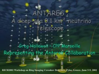
Horizontal layout The ANTARES detector Storey Buoy 40 km electro-optical cable to shore 350 m 12 lines 25 storey/line 3 PMT/storey 900 PMTs in total Junction box 100 m Submersible 12 lines 3x25 PMT/line Interlink cable 60-75 m Anchor(BSS) Francisco Salesa
The ANTARES devices The Storey The LED Beacon for time calibration purposes. The ANTARES 10’’ PMT is housed in the Optical Module. A glass sphere protects it from high pressures. A μ-metal cage shields against the Earth magnetic field. The Local Control Module houses, in a titanium frame, the electronic cards devised for the readout of the three OMs . The Hydrophone (Rx)for positioning. Francisco Salesa
The ANTARES devices • A 40 km electro-optical cable links the shore station and the detector. • With 58 mm diameter, it is made up of 48 monomode pure silica fibre optics. • It provides the power and clock & commands signal to the junction box. BSS • Junction box made up of titanium, splits the clock and commands signals to the BSS of each line. • The BSSanchors the line and controls the power and data transmission. It also contains some instruments as a pressure sensor or RxTx hydrophone. Junction box Francisco Salesa
An internal LED monitors the transit time of the PMT. 60 m 60 m 300 m 300 m Time calibration • The Optical beacons are external light sources for timing calibration The Laser beacon emits at 532 nm and is placed at the anchor of the MILOM. The LED beacon, emits blue light (472 nm) from 36 pulsed LEDs. Four beacons are placed along each line. • All the OMs are illuminated by OB. The time off-sets measured in the laboratory can be checked in-situ. Francisco Salesa
Positioning The positioning system consists of an acoustic system, compasses and tiltmeters. The acoustic system uses sound signals in the 40-60 kHz range. The tiltmeters provide the pitch and roll. The compasses, the magnetic field and heading. Pitch Roll Autonomous Pyramid Fixed RxTx (transponder hydrophones) located in each BSS. In addition, 3 autonomous transponder pyramids are also fixed at the sea bed and located around the detector strings. BSS Five Rx (receiving hydrophones) distributed in each line. One tiltmeter-compass card per storey. Electro-optical cable to shore The Positioning System provides 10cm accuracy for each OM. Francisco Salesa
Effective area Detector performance • Angular resolution Effective area means the area of 100% efficient flat surface. Depends on the incident neutrino flux. Muon effective area is the relevant quantity to compare between experiments. The maximum area is reached at 10-100 TeV. At high energies the Earth becomes opaque to neutrinos. mrec, ntrue mrec, mtrue m q n reconstruction kinematics • Below 10 TeV is dominated by the kinematic angle qmu. • Over 10 TeV dominated by reconstruction (calibration, electronics, etc.) Earth opacity effect. Francisco Salesa
Point-like source candidates Galactic centre SNR RX J1713-3946 TeV sources candidates. Vela pulsar • ANTARES will observe 3π sr (galactic centre visible 67% of the time). • Complementary to AMANDA/IceCube at the South Pole (0.6π sr overlap). • HESS observations of RX J1713-3946 SNR spectrum show a presumably hadronic scenario, thus neutrino emission is expected (Nature 432 (2004) 75). Francisco Salesa
Source detection • Diffuse flux detection. • Point-like source detection. Experimental limits for different experiments assuming E-2 spectrum. Comparison between experiments for point-like sources detection. Francisco Salesa
Collaboration milestones & schedule R&D • 1996-1999: R&D and site evaluation period. • November 1999 & summer 2000: prototype lines • October 2001:Electro-optical cable deployment. • December 2002:Junction box (JB) connection. • December 2002:PSL (Prototype Sector Line) deployment. • February 2003:MIL (Mini Instrumentation Line). • March 2003:MIL & PSL connection to JB. • May and July 2003:MIL & PSL recovering. PROTOTYPES • March 2005:Line0 (test of mechanics) & MILOM (Mini Instrumentation Line with Optical Modules) deployment. • April 2005:MILOM connection. • May 2005:Line0 recovering. • February 2006:Line1 deployment. • March 2006:Line1 connection (Data analysis of Line 1 in progress). FINAL DESIGN • Line 2 deployment foreseen by July 2006. • Lines 3 and 4 before the end of this year. • The whole detector will by finished by end 2007. • Science operation from 2007. FUTURE Francisco Salesa
Site evaluation results measured with pulsed LEDs • Optical background. • Biofouling. Continuous component due to 40K decay (salt) and bacteria colonies. Burst (20% over baseline) due to bioluminiscense abyssal creatures. • Water properties. At 90º a global loss of ~ 1.5% is expected in one year with a saturation tendency. Francisco Salesa
MILOM line MILOM sketch • 3 Storeys. • Instrumentation line + OMs: • 4 OMs. • 2 LED Beacons. • 1 Laser beacon. • 1Rx hydrophone. • 1RxTx transponder. • Sound velocimeter. • Seismometer. • Acoustic Doppler Current Profiler. • Conductivity Temperature probe. • Successfully test of DAQ and electronics. • MILOM is still operating. Francisco Salesa
Site properties: Results from MILOM summer autumn Bursts ~120 kHz Baseline ~60 kHz Seasonal variations Example of data taking rate Baseline evolution with time Correlation with currents has been noticed Currents < 20 cm/s ~5 cm/s on average Water current velocity evolution with time Heading of the three MILOM storeys Francisco Salesa
Results from MILOM • Spatial Calibration: • Charge Calibration: WF signal example. Distance from autonomous line (RxTx) to MILOM RxTx, evolution with time. 96 m 175 m Evolution with time of the normalized charge. Francisco Salesa
Results from MILOM • Time Calibration: The rate measured of these coincidences is ~13 Hz which is in agreement with the estimations. Internal LED Dt evolution with time 40K coincidences between OMs. Storey OM signal – beacon PMT time difference for each OM. MILOM LED beacon Francisco Salesa
Line 1 deployment 25 storeys + 1 BSS LED beacon RxTx Buoy OM Line anchor Francisco Salesa
Line 1 deployment March 2006 February 2006 Francisco Salesa
First muons reconstructed with Line 1 Antares preliminary Antares preliminary Antares preliminary Result of Fit • Run / Event • Zenith angle • Fit probability • 21240 / 12505 • q= 101o • P(c2,ndf) = 0.88 • 21240 / 12527 • q= 172o • P(c2,ndf) = 0.94 • 21240 / 12845 • q= 72o • P(c2,ndf) = 0.37 z [m] • Triggered hits • Hits used in fit • Snapshot hits + t [ns] Francisco Salesa
Atmospheric Muon Bundles Montecarlo Reconstruction Antares preliminary Antares preliminary Time residuals s = 7.8 ns Time residuals s = 7.8 ns Number of events [arbitrary units] Number of events [arbitrary units] Dt [ns] Dt [ns] Antares preliminary Antares preliminary Number of events [arbitrary units] Number of events [arbitrary units] P(c2,ndf) P(c2,ndf) Francisco Salesa
Line 1 calibration Line 1 s = 2.6 ns MILOM LED Optical Beacon ~150 m Number of events [arbitrary units] s = 0.7 ns ~70 m Dt [ns] Francisco Salesa
Future: KM3NeT • A km3 (or larger) is the desirable volume for a neutrino telescope. • The KM3NeT Design Study has been approved by the European Union. • The three Mediterranean experiments collaborate in this study: ANTARES+NEMO+NESTOR. • Complementary to IceCube at the South Pole in order to cover the whole sky. • Technical Design Report early 2009. Francisco Salesa
Conclusions • The deployment of Line 1 and the on-going data taking is a great success. • Currently ANTARES is operating with the MILOM and Line 1 simultaneously. • 2nd line deployment this summer, the whole detector will by finished by end 2007. • Atmospheric muons have been reconstructed. Presently working on angular distributions. • ANTARES will cover the South sky with an expected angular accuracy of 0.3º thanks to the optical properties of water and the good detector performances (electronics, calibration, etc). Francisco Salesa