Download
1 / 32
330 likes | 503 Vues
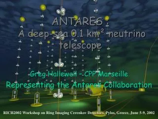
ANTARES : A deep-sea 0.1 km² neutrino telescope. Greg Hallewell – CPP Marseille Representing the Antares Collaboration. RICH2002 Workshop on Ring Imaging Cerenkov Detectors, Pylos, Greece, June 5-9, 2002. CPPM, Marseille DSM/DAPNIA/CEA, Saclay C.O.M. Marseille IFREMER, Toulon/Brest

E N D
ANTARES : A deep-sea 0.1 km² neutrino telescope Greg Hallewell – CPP Marseille Representing the Antares Collaboration RICH2002 Workshop on Ring Imaging Cerenkov Detectors, Pylos, Greece, June 5-9, 2002
CPPM, Marseille • DSM/DAPNIA/CEA, Saclay • C.O.M. Marseille • IFREMER, Toulon/Brest • LAM, Marseille • IReS, Strasbourg • Univ. de H.-A., Mulhouse • ISITV, Toulon • Observatoire de la Côte d’Azur • University of Bari • University of Bologna • University of Catania • LNS – Catania • University of Rome • University of Genova ANTARES Collaboration • NIKHEF, Amsterdam • University of Sheffield • ITEP, Moscow • IFIC, Valencia • Universitat Erlangen
Contents • Detector Overview • Detector Principal Components • Site Selected and Ocean Backgrounds • 40K, bioluminescence, light absorption • 4) “Demonstrator” Line • 7 PMTs, m hyperbolic reconstruction • 5) Time and Position Calibration • m reconstruction from PM signals with arrival times known to ~1 ns • acoustic transponder net, LED and laser beacons • 6) Sea Instrumentation Line • current profile, salinity, light absorption, P,T, sound velocimeter • 7) “Sector” Line Deployment • 8) Conculsions
(1.1) Detection Principle Lattice of 900 PMTs in “Optical Modules” m track direction from arrival time of light Neutrino direction: 0.7o / E0.6(TeV) m energy from energy loss and range Typ. 1g per PMT 40m from m trajectory Cerenkov light isochrone in seawater muon ANTARESDetector interaction A 0.1km2 detector should record ~ 1-2000 medium energy cosmic neutrinosper year (En > 300 GeV). neutrino
(1.2)Scientific Motivation Medium Energy (10 GeV < E < 1 TeV) Low Energy (10 GeV < E < 100 GeV) High Energy (E> 1 TeV) neutralino search (signal from annihilating WIMPs in the Earth, the Sun and the Galaxy) from galactic and extra-galactic sources (x-ray binaries, micro-quasars, SNR, AGN, GRB) oscillations (observation of first oscillation minimum from atmospheric ) +Oceanography - measurements of oceanographic parameters of the deep sea - studies of bioluminescence
Energy resolution Angular resolution 0.1 km² Detector : Expected performance • Including effects of reconstruction and selection, PMT TTS, positioning, timing calibration accuracy and scattering. • Below ~10 TeVangular error is dominated by - physical angle. • Above ~10 TeV angular accuracy is better than 0.4° (reconstruction error). • E/E 3 (E 1 TeV) • Below E ~ 100 GeV energy estimation via muon range measurement.
10 lines of 90 PMTs • 6 sectors/line (350m) • 5 storeys/sector(60m) • 3 PMTs/storey(12m) Time calibrationLED Beacon (1 / sector) Optical Moduletriplet Local electronics Hydrophone (1 / sector) ANTARES 0.1km2 detector 2400m 40 km cable to shore 12 m 350 m 100 m Junction box 60 m Readout cables
String Control/Power Module: - string power supplies - data acquisition: 6 sectors DWDM 6x1Gb/s on 1 fibre Interlink cable, - wet-mateable connector: 4 optofibres+ 2 power conductors Bottom String Structure - acoustic string release, acoustic positioning transponder (2) Principal Components: A Detector Line Buoy Electro-mechanical Cable - mechanical support (kevlar core) with optical fibres and power conductors 90 PMTs/line 6 sectors of 5 storeys of 3PMTs LED Beacon (4 per line) • 3 Optical Modules/storey • - 10” PMT, active base, LED internal calibration system • 1 Local Control Module; • “ARS” front end ASIC (amplitude, 1GHz time sampling)/PMT; • Tiltmeter (line shape in current) & compass (line torque) 12m Master Local Control Module: - acoustic positioning (1 hydrophone / sector) - data acquisition: 5 storeys sector ethernet 1Gb/s 100m Sea bed
Quantum Efficiency Latt(Sphere) (LoBoro): cm Latt(Gel): cm (2.1) Principal Components: Optical Module & PM LED pulser Optical gel Photomultipler: 10” Hamamatsu R7081-20 Sensitive area > 500 cm2; 14 stages; 2.108 Gain @ 2500V; Transit Time: typ 60ns @ 1750V (–2.5ns/100V) (Regularly Measured by LED pulser on each tube) Transit Time Spread: s 1.3 ns(spec.):V fixed; Dark Count Rate (0.3 pe equ. Thr.): < 10kHz; Pulse Shape: Rise Time < 5 ns, FWHM < 12 ns Active (C-W) PMT Base (ISEG) Glass sphere (Nautilus) Mu metal magnetic shield
Some Detector Specificatons Cerenkov signature: Timing of cone arrival at PMTs on strings: hyperbolic fit PMT positions need to be known to ~20 cm (1 ns in seawater) # OM hits depends on range of muon Detector Positioning Resolution Hits to s <1 ns to be small compared with dispersive limits in seawater of ~ 1.6 ns over ~ 40 m optical path length achieved by: acoustic transponder net: string profile in undersea current, inclinometers (pitch, yaw) & compasses (heading: OM rotation angle around string ): (1 per “storey”) Timing Resolution on OM LED Pulser in each OM, LED & Laser beacons:Goal < 0.5 ns
Timing Resolution: electronic signals directly into ARS Timing Resolution: attenuated laser signals OM ARS (2.3) ARS Timing Resolution (May ’02)
(3) The ANTARES Site Antares Site: 40Km SE Toulon (42º50’N, 6º10’E) Depth 2400m Shore Base La Seyne-sur-Mer 40 km Submarine cable -2400m
Line connections Victor (ROV) 1 2 6 5 3 4 10 9 8 7 13 14 11 12 (3.2) Site: Sea Floor Layout, Vehicle Resources Site inspection: “Cyana” (Manned Submersible) Line sea floor configuration Wet-Mateable Connector (@250 bar H2O) At Line Sea Anchor Submarine cable: ALCATEL
Variable distance between LED and PMT “ascenseur” (3.4) Water optical properties: Transparency Need in-situ on line monitoring (instrumentation line)
(3.5) Water Properties: Optical Backgrounds • Cerenkov Light: • from Atmospheric (Downgoing)m’s • (~400g cm-1: 300<l<600 nm) • ( <Em> ~350 GeV:mrate 10-30 Hz) • (106 * rate of upgoingmfromn) • (2) Sea Optical background: • ~ 60 kHz on 10” PMT mainly 40K • Bioluminescence • bursts(o~MHz), locally-correlated (typ 1 storey, 3 PMTs) • ~ few % of the time • + Bottom Current Dependent • Bottom Currents Measured • typ. < 5% dead time/ PMT
December 98 : successful undersea electrical connection test of detector anchor performed at 2400m depth by IFREMER submarine vehicle “Nautile” (ex-Titanic expeditions) (4) Full Demonstrator Line (’98-’00) • First (350m) line equipped with 16 pairs of Glass Spheres • Summer 98 :successful deployment test at 2300m depth performed with Dynamical Positioning ship • December 99-June 00 :demonstrator equipped with 7 PMTs + acoustic positioning system linked to shore station by electro-optical cable • 50,000 atmospheric m’s reconstructed
(4.1) Muons on “Demonstrator line” • 50,000 events with 7-fold coincidences • (>1300 reconstructed events per day) • Zenith from 4 par. Hyperbolic fit of depth vs. PMT signal timestamp • 40K hits filtered out by software • MC agrees with data (multimuons, ghosts) No reconstructed events q < 45º
1 of 3 rangemeters Devices Accuracy () Inter-rangemeter ~1 cm 5cm Inter-Transponder ~ 1 cm Rang.-Transponder 3 cm Time (min) (5.1) 40-60 kHz Acoustic positioning system 4 transponders Self-Cal. Y coord. Range 3-2 (m) Require Positioning Accuracy < 1 ns (1 ns = 22cm in seawater). Triangulation allows 5 cm accuracy
Buoy LCM+acoustics Rx2 LCM LCM LED beacon MLCM LCM+acoustics Rx1 SCM/SPM, acoustics Rx/Tx BSS (6) The Sector Line: Deployment for late ‘02 Optical Module Local Control Module Optical module frame Junction Box InterLink cable to shore station
(7) The Mini Instrumentation Line Mechanical Cable • Current profiler • ADCP 300 kHz of RDI • Orientated downwards • Current profile for ~150 m depth • Resolution: ~ 0.5 cm/s • RS232 interface • Temperature/Salinity: • Model 37-SI MicroCAT • Resolution : 10-4 °C, 10-4 S/m • RS232 interface • Transmissionmeter • CSTAR of Wetlabs • Measures over 25cm • large azimuthal range for labs, lscatt Sound Velocimeter ADCP Current Profiler Electro Mechanical Cable 3 fibres for DAQ 100m Acoustic Positioning Modules (receivers) Optical Beacon CTD CSTAR Electro Mechanical Cable 2 fibres for DAQ, 1 for clock 100m LASER Beacon Acoustic Positioning Modules 2 fibres for DAQ 1 for clock JB
ANTARES Timeline “Demonstrator” line deployment and operation Collaboration formed Site evaluation programme to select a suitable site 1996 1997 1998 1999 2000 _________________ 2001 2002 2003 2004 2005 Deployment of lines 1 to 10 Sector Line deployment Sector Line mechanical test 0.1km2 detector to complete EO Cable deployed and tested Technical design report completed
(8) Conclusion ANTARES has made excellent progress over the past 4 years : • Site environmental characterisationOK • Tests of marine technologiesunder control • Deployment and operation of Demonstrator String • Down-going muons reconstructed in demonstrator • Expanding Collaboration • ANTARES has entered Phase II of its programme: • the design, the installation and commissioning of a 10-string 0.1 km² detector in 2002-2004 • main electro-optical sea cable successfully deployed • - sector line deployment Sept 2002 • Major step forwardtowardsa km-scale neutrino telescope in the Mediterranean
THE END (possible extras follow)
The angular resolution of the detector depends on reconstruction algorithms selection programs timing accuracy (PMT timing error, positional error on OMs, timing calibration error) Above 10 TeV the neutrino pointing accuracy is 0.4 degrees or better including scattering effects Note: at high energy the error is dominated by reconstruction errors, at low energy by the angle between the muon and neutrino Angular Resolution
(2.1) Principal Components: Optical Module LED pulser Optical gel Photomultipler: 10” Hamamatsu R7081-20 Active (C-W) PMT Base (ISEG) Glass sphere (Nautilus) Mu metal magnetic shield
(2.2) Principal Components: Hamamatsu R7081-20 Characteristics Sensitive area > 500 cm2; 14 stages; 2.108 Gain @ 2500V; Transit Time: typ 60ns @ 1750V (–2.5ns/100V) (Regularly Measured by LED pulser on each tube) Transit Time Spread: s 1.3 ns(spec.):V fixed; Dark Count Rate (threshold 0.3 pe equ.): < 10kHz; Pulse Shape: Rise Time < 5 ns, FWHM < 12 ns Quantum Efficiency Latt(Sphere) (LoBoro): cm Latt(Gel): cm T > 88%
7 Mb/s OM OM OM DWDM DWDM 125 Mb/s Ethernet Switch 75 kb/s 75 Mb/s DataWriter CPU (2.4) Data Flow Architecture “Local Control Module” LCM 25 Mb/s LCM • OFFSHORE • Communication between offshore LCM processors (MPC8xx) • and onshore farm (~100 PCs) using Ethernet protocol via • optical fibres • All data to shore- if bandwidth saturated, an OFFSHORE • TRIGGER can be activated to reduce dataflow to just local • coincidences • Bandwidth of data transmission maximised using DWDM • Dense Wavelength Division Multiplexing • - Each sector of a string assigned a colour (7 colours/string) • - At SCM all colours multiplexed to one pair of fibres LCM “Master (sector) Local Control Module” MLCM LCM 125 Mb/s “String Control Module” SCM 750 Mb/s from other lines JB 7.5 Gb/s • ONSHORE • The colours of each line are • demultiplexed • All data of current time frame (10ms) • assigned to single CPU • Each PCs run the DataFilter program • which accepts events with time correlated • hits 7.5 Mb/s
Energy Resolution Different techniques are used in different energy regimes Below 100 GeV the energy can be estimated from the range of the muon:sE ~ 3 GeV Use of the hadronic shower energy may improve energy resolution at medium and low E At energies above 1 TeV the muon energy loss is dominated by catastrophic energy loss (bremss., pair production) which increases with energy. A truncated mean parametrization is used The corresponding energy resolution is typically a factor of 3 to 4 for E > 1 TeV
LED (Blue) Beacon (4 per line ) (illuminates several stories of neighboring lines): MiniPMT for time reference LED pulsers 5.106 8.107g per pulse @ 470nm, Trise 1.82 ns; FWHM 4.56.5 ns Green Laser Beacon (Instrumentation line anchor) (illuminates lower stories of most lines): Fast pin diode for time reference Nanolase NG-10120-120 laser head + Diffuser 532 nm; 1 mJ/pulse, Trise 1.82 ns; FWHM 0.8 ns (5.2) Optical Beacons fortiming calibration precision 0.5 ns:cf arrival time precision of OM ~ 1 ns
3.5 sr of sky covered • 0.5 sr overlap with Amanda • Galactic Centre surveyed • Need neutrino telescopesin both hemispheres (3) The ANTARES Site Antares Site: 40Km SE Toulon (42º50’N, 6º10’E) Depth 2400m Shore Base La Seyne-sur-Mer 40 km Submarine cable -2400m
Variable distance between LED and PMT “ascenseur” (3.4) Water optical properties: Transparency Need in-situ on line monitoring (instrumentation line)
labs~ 55-65 m ;lscat > 100 mat large angles Water Transparency