Counter/Timer/PWM
Counter/Timer/PWM. Counter. counter is a device which stores the number of times a particular event or process has occurred synchronous/asynchronous pulse up counter/down Counter. count 범위 : 0~2 N -1. Timer. timer is a specialized type of clock

Counter/Timer/PWM
E N D
Presentation Transcript
Counter • counter is a device which stores the number of times a particular event or process has occurred • synchronous/asynchronous pulse • up counter/down Counter count 범위 : 0~2N-1
Timer • timer is a specialized type of clock • synchronous counter with fixed frequency clock Tclk = 1/fclk Timer의 최소단위 : Tclk 최대 측정 시간 : (2N-1)Tclk
Example • counter : how many tablet ? • timer : how long ?
Counter/Timer in Atmega128 • 8-bit Timer/Counter • TCNT0, TCNT2 • Counting 범위 : 0~255 • 16-bit Timer/Counter • TCNT1H & TCNT1L, TCNT3H & TCNT3L • Counting 범위 : 0~216 – 1 = 65535
Basic Operation • fclk = 1 Mhz, N(prescale) = 100 • Tclk = 1 uSec • ftimer = fclk/N = 10 kHz • Ttimer = 100 uSec 8 bit / 16 bit clk Counter/timer (TCNTn) prescaler fclk ftimer = fclk/N Tclk = 1/fclk Ttimer = N/fclk
Basic Operation & Timer Interrupt • normal mode : overflow interrupt • clear time on compare match (CTC) mode : output compare interrupt
8 bit Timer/Counter Register 관련 Register • TCCRn : Timer/Counter Control Register • 예) TCCR0 = 0x05 • ftimer = fclk /128 = 7372800/128 = 57600 Hz • Ttimer = 1/57600
8 bit Timer/Counter Register 관련 Register • TCNTn : Timer/Counter Register • Overflow Interrupt • 예) TCNT0 = 0x27 • 구간 = 0xFF-0x27 = 0xD8 = 216 • 216 * Ttimer마다인터럽트 발생이 가능함
8 bit Timer/Counter Register 관련 Register • OCRn : Output Compare Register • Output Compare Interrupt • 예) OCR0 = 0xA2 • 구간 = 0xA2 = 162 • 162 * Ttimer마다인터럽트 발생이 가능함
8 bit Timer/Counter Register 관련 Register • TIMSK : Timer/Counter Interrupt Mask Register • TOIE0 bit : Overflow Interrupt Enable • OCIE0 bit : Output Compare Interrupt Enable • ETIMSK : Extended Timer/Counter Interrupt Mask Register
16 bit Timer/Counter Register 관련 Register • Timer/Counter Control Register • TCCRnA • TCCRnB • TCCRnC
16 bit Timer/Counter Register 관련 Register • Clock Selection Bit : CSn0 ~ CSn2 in TCCRnB
16 bit Timer/Counter Register 관련 Register • TCNTnH & TCNTnL
16 bit Timer/Counter Register 관련 Register • Output Compare Register • OCRnAH & OCRnAH • OCRnBH & OCRnBH • OCRnCH & OCRnCH
Timer Interrupt Example • Mode : normal mode (overflow interrupt) • Interrupt 간격 : 500mSec • fclk = 7372800 Hz • 0.5초 : 3686400 • 16bit counter = 216 – 1 = 65535 • prescale : 1024 • 3686400/1024 = 3600 => 0xE10 • 0xFFFF-0xE10 = 0xF1EF • TCCR1A = 0x00; TCCR1B = 0x05; TCCR1C = 0x00; • TCNT1H = 0xF1; TCNT1L = 0xEF; • TIMSK = 0x04;
Timer Interrupt Example #include <avr/io.h> #include <avr/interrupt.h> int main(){ DDRD = 0x18; TCCR1A = 0x00; TCCR1B = 0x05; TCCR1C = 0x00; TCNT1H = 0xF1; TCNT1L = 0xEF; TIMSK = 0x04; sei(); while(1); return 0; }
Timer Interrupt Service Routine ISR(TIMER1_OVF_vect) { static char cnt = 0; // static 은 이전 값을 유지 함 cnt++; cnt %= 2; if( cnt == 0 ) PORTD &= 0xEF; else PORTD |= 0x10; TCNT1H = 0xF1; TCNT1L = 0xEF; }
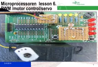
연습 • 다양한 시간으로 lamp 구동 • 1초 간격으로 • left motor 전진 • right motor 전진 • left motor 정지 • left motor 후진 • right motor 정지 • right motor 후진 • leftmotor 정지 • right motor 정지 • 이하 반복
Timer Interrupt Example (II) • Mode : clear time on compare match (CTC) mode (output compare interrupt) • Interrupt 간격 : 250mSec • fclk = 7372800 Hz • 0.25초 : 1843200 • 16bit counter = 216 – 1 = 65535 • prescale : 1024 • 1843200 /1024 = 1800 => 0x0708 • TCCR1A = 0x00; TCCR1B = 0x0D; TCCR1C = 0x00; • OCR1A =0x0708; (OCR1AH = 0x07; OCR1AL = 0x08; ) • TIMSK = 0x10;
CTC mode (output compare interrupt) • Which counter ? • TCNT0, TCNT1, TCNT2, TCNT3 ? • Timer/Counter Control Register • TCCRnA / TCCRnB / TCCRnC = ? • Output Compare Register • OCRnA / OCRnB / OCRnC = ? • Timer/Counter Interrupt Mask Register • TIMSK ?
CTC mode (output compare interrupt) • Timer/Counter Control Register • TCCRnA • TCCRnB • TCCRnC 0 0 Timer/counter mode prescale 0 1 1 0 1
CTC mode (output compare interrupt) • Timer/counter Mode of Operation
CTC mode (output compare interrupt) • Output Compare Register • OCRnA / OCRnB / OCRnC = ? • TIMSK : Timer/Counter Interrupt Mask Register
Timer Interrupt Example #include <avr/io.h> #include <avr/interrupt.h> int main(){ DDRD = 0x18; TCCR1A = 0x00; TCCR1B = 0x0D; TCCR1C = 0x00; OCR1A = 0x0708 TIMSK = 0x10; sei(); while(1); return 0; }
Timer Interrupt Service Routine ISR(TIMER1_COMPA_vect) { static char cnt = 0; // static 은 이전 값을 유지 함 cnt++; cnt %= 2; if( cnt == 0 ) PORTD &= 0xEF; else PORTD |= 0x10; }
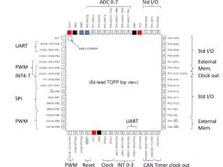
Timer/Counter의 Input & Output • Input • Counter : asynchronous pulse • Timer : external clock • Output • Waveform • PWM : Pulse Width Modulation • External Input/Output • I/O Port에 배정
Timer/Counter의 Input & Output • TCNT0 : 8bit Counter • No input • Output : OC0 (PB4) • TCNT1 : 16bit Counter • Input : T1 (PD6) • Output : OC1A(PB5), OC1B (PB6), OC1C(PB7) • TCNT2 : 8bit Counter • Input : T2(PD7) • Output : OC2 (PB7) • TCNT3 : 16bit Counter • Input : T3 (PE6) • Output : OC3A(PE3), OC3B (PE4), OC3C(PE5)
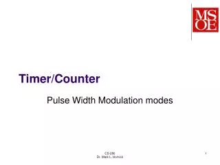
Timer/Count Mode • normal mode : overflow interrupt • clear time on compare match (CTC) mode : output compare interrupt • Fast PWM Mode
Timer/Count Mode • Phase Correct PWM Mode
DC 모터의 가감속 제어 • DC 모터의속도제어 • DC 모터의 전달함수 • 정상 상태 속도는 입력 전압에 비례
Pulse Width Modulation (PWM, 펄스폭변조) • commonly used technique for controlling power to an electrical device • power delivery, voltage regulation, telecommunication, … • 신호 크기에 비례하는 pulse width or duty cycle
Pulse Width Modulation (PWM, 펄스폭변조) • Why PWM ? • difficult to amplify a voltage with appropriate power • compact and low cost means for applying adjustable power for many devices • Principle of PWM • 전달되는 power는 duty cycle에 비례 • PWM frequency
PWM in ATmega128 • Fast PWM mode/Phase Correct PWM Mode • TCNT0 • OC0 (PB4) • TCNT1 • OC1A(PB5), OC1B (PB6), OC1C(PB7) • TCNT2 • OC2 (PB7) • TCNT3 : 16bit Counter • OC3A(PE3), OC3B (PE4), OC3C(PE5) • OC1B (PB6) : Left Motor Enable • OC1C (PB7) : Right Motor Enable • TCNT1 => PWM으로 사용
PWM Example • PWM mode : Fast PWM 10 bit mode • PWM frequency • motor와 motor driver의 주파수 특성 : ? • fclk = 7372800 Hz • N(prescale) = 8 • TOP = 210-1
PWM Example • Timer/Counter Control Register • TCCRnA • TCCRnB • TCCRnC 1 0 1 0 1 1 Timer/counter mode prescale 0 1 0 1 0
PWM Example #include <avr/io.h> int main(){ DDRB = 0xCF; PORTB = 0x06; TCCR1A = 0x2B; TCCR1B = 0x0A; TCCR1C = 0x00; OCR1B = 0x00; /* 원하는 속도를 기입 0x000 ~ 0x3FF */ OCR1C = 0x00; /* 원하는 속도를 기입 0x000 ~ 0x3FF */ while(1); return 0; }
실습 과제 • 좌우 모터에 대해 • 저속/중속/고속을 정의 • 전진/후진/정지를 정의 • Left/Right Switch를 이용하여 Motor Disable (Interrupt) • USART 통신을 이용하여 제어 (Interrupt)